12 volt Electrics
House Battery
Following a major melt-down (literally – one cell collapsed, causing gassing, heating and major swelling) of the original Amp-Tech AT121000D deep cycle battery, it was replaced on 28 November 2008 with a Fullriver HGL120-12B AGM (Absorbed Glass Matting) VRLA (Valve Regulated Lead Acid) battery (the only Fullriver model available at the time and place). The battery is claimed to have a 6–10 year life in ideal conditions. Its 120 Ah rating is specified for a 20 h drain (i.e., 6 Amp). The size is 331 mm L x 175 mm W x 218 mm TH (the same size as the previous 100 Ah battery).
The battery was housed in a plastic battery box next to the stove under the bed and is permanently vented to the (driver's) outside by a 50 mm flexible plastic pipe.
AGMs are bulk charged at constant current (or whatever the solar panels can supply through the Solar Controller if it is cloudy) until the battery voltage rises to around 14.4V, after which the voltage is held at that value during the absorption cycle. After a certain time the charger switches to the float mode, dropping the voltage to ~13.8V.
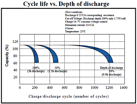
Every discharge/charge cycle reduces the life of the battery. The Fullriver HGL series of batteries have a cycle life as shown here for ideal conditions. It seems a good idea to maintain a ~70% state of charge when the battery is in use (~30% depth of discharge), however reaching the occasional 50% state of charge is no problem so long as the battery is recharged without delay by an adequate independent battery charger or solar cell arrangement.
Mid 2013: four and a half years later, the Fullriver AGM was down in capacity and its terminal voltage was rising too quickly under charge so it was not accepting much energy. It was replaced with a 100 Ah Winston LiFeYPO4 type from Basicly Natural. The cost was $1.40/Ah/cell for a total of $622 + freight.
Because of its charging characteristics, a lithium battery is much less forgiving of over charging than a lead-acid battery. It requires a battery management system. With a lot of help from T1 Terry Covill I have implemented one and it works very well. The major changes I designed and built are described below. The reasons for these changes and some implementation details are described on the lithium battery page. The page is Passworded to protect the information that was shared in confidence by Terry and some of the over 100 people who contributed to a closed Web site on the topic.
The Winston Lithium cells are claimed to have (p19) a life expectancy of 3000–5000 cycles (or 10 years) if discharged and charged at a rate of 0.5C (50 A for a 100 Ah cell). If they achieve even half that I will be very happy! Typically, they can be discharged to 20% of capacity, giving a usable 80 Ah, about twice that for the 120 Ah AGM it replaces. It is alright to leave them in a partially chargerd state for long periods.
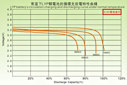
Peukert Exponent
The state of charge of the battery is measured by integrating the (signed) current input to the battery over time, adjusting for discharge rate. Some expensive battery monitors have this facility. A project to do that for the Applause motorhome, but without adjustment, is described on another page. However, the multi-function panel meter (described later on this page) now does this and that page is for historical interest only. Since the Peukert exponent of a lithium battery is close to unity (1.05 is the generally accepted value) practically no adjustment for discharge rate is warranted.
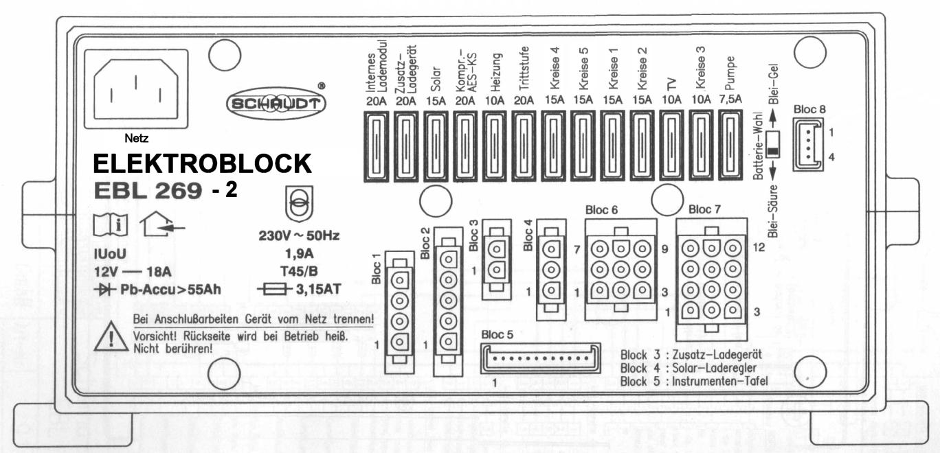
Elektroblock EBL 269-2
The Schaudt EBL 269-2 Elektroblock charges the battery and supplies 12 V appliances with power. Its functions include:
- The 18 A LAS 1218 charger module
- The 12 V distribution
- Fuses for the 12 V circuits
- Other control and monitoring functions.
The front panel of the Schaudt EBL 269-2 from the documentation (you may need to delete '.sav' from the name once downloaded):
Battery Charger LAS 1218
The LAS 1218 is a IUoU charger. The capital letters indicate a charge phase during which that electrical property (I for current, U for voltage, W for power) is constant. An IUoU charger has three phases: constant current, constant voltage, constant voltage. The second (trickle charge) phase typically has a lower voltage than phase 2. The following diagram shows this.
Control Panel
The control and switch panel is a Schaudt LT400.
Some comments:
- Eight-step voltage indication of house and starter batteries. These are not very accurate, and seem sensitive to temperature.
- Four-step indication of water tank fill levels for fresh and grey water tanks but these are VERY unreliable.
- 12 V Main switch with indicator, Accessories, Lighting and Water switches.
- The PCB includes provision for monitoring the current shunt in the Elektroblock. This is implemented as described later.
Elektroblock Circuit Diagram
A full circuit diagram is included in Schaudt's description of the EBL 269 and the original is repeated here (click it for a larger version). Note that the circuit has now been modified to help manage charging of the lithium battery. The changes are presented later.
Two heavy cable pairs run from a battery/alternator connection in the engine bay directly to the Elektroblock. A single (yellow) cable runs from a D+ alternator connection in the engine bay to the Elektroblock (block 2, pin 3). One of the pairs powers the fridge (through block 2, pin 1) when the D+ line is at 12 V. The other pair provides alternator charge to the house battery (through connector E20-3F on the back of the Elektroblock) when the D+ line is at 12 V and also provides charge current from the Elektroblock to the starter battery when the van is on 230 V mains hookup.
As received, A'van had wired the side step into the water supply circuit, controlled from the Switch Panel. This has been corrected as part of a redesign of the side step control setup (see the changes here) by wiring it to the designated pins of Block 6, which otherwise was not being used at all.
The Schaudt description notes that all consumers of 12 V are switched except:
- Heater
- Step
- AES/compressor refrigerator
- Circuit 1/4 and Circuit 5.
The Schaudt description also notes that:
- A relay in the Elektroblock supplies the AES/compressor refrigerator with power from the starter battery when the vehicle engine is running and the D+ line from the alternator is high (12 V).
- The refrigerator is powered by the house battery when the vehicle engine is switched off.
- An automatic float charge for the starter battery at up to 2 A occurs when the 240 V mains supply is connected to the Elektroblock.
A Note on the D+ Line
The vehicle alternator includes B+ and D+ terminals. The D+ terminal is connected to one side of the ignition warning lamp in the vehicle; the other side of the warning lamp is connected to the starter battery positive terminal via the ignition key switch. When the key switch is initially turned ON before starting the engine some small amps will flow through the key switch, through the bulb and via the D+ terminal of the alternator through the slip rings and rotor winding so that the alternator can initially excite. At this time the voltage on the D+ terminal is close to zero. As soon as the engine starts and the alternator starts to charge the starter battery from the B+ terminal, the voltage at the D+ terminal goes to 12 V or more. This voltage activates a relay in the Elektroblock to connect the output voltage of the alternator at B+ to the leisure battery positive terminal. The Elektroblock also uses this D+ signal to energise another relay to connect the compressor fridge to the starter battery/alternator.
Changes for Charging the Lithium Battery
Each of the three charge sources, mains, alternator and solar, are well behaved at the pack level — they charge the lithium battery to a state where the pack voltage is no more than 14.2V. However, possible cell imbalances mean that the charging needs to be managed to ensure no single cell reaches a voltage above 3.6V (see reference).
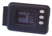
The lithium battery pack voltage and cell voltages are monitored by and managed by two Junsi Cell-Log 8M (or model 8S with data logging capability). This low-cost device can monitor the four battery cells at once, and can be set to sound an alarm and switch an open-collector transistor if a cell or the pack goes over or under set voltages.
The Junsi Cell-Log in the battery compartment is set to alarm whenever the pack or a cell goes over-voltage or under-voltage. The output of the Cell-Log triggers relays to cut the charge sources (High Voltage Cut – HVC) or to cut the loads (Low Voltage Cut – LVC). A delay of around three minutes is imposed on the HVC to allow the loads to reduce the battery voltage a little before retesting. This delay provides the necessary hysteresis so the Cell-Log does not repeatedly and rapidly go between alarm and normal states. In the process, the highest voltage cell is dragged down more quickly than the others, since it is the one with the highest surface charge — the result is the cells tend towards balance.
After a lot of discussion with Terry Covill I have modified the Elektroblock to implement the HVC strategy.
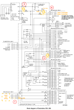
- The three pin Block 4 has been repurposed as the 12V supply to, and signal from, the Cell-Log and delay board. The signal on Pin 2 activates three new relays in the Elektroblock (Jaycar 30A horn relays –SPDT). Each relay draws 140mA when activated and then adds to the load on the battery.
- A relay interrupts the integrated LAS 1218 battery charger output. The line that went from A8 on the charger to A2 on the main board now goes from the relay Common to A2 and a new wire from A8 goes to the relay NC terminal.
- A relay cuts the D+ input from the alternator. Cutting the D+ input cuts the integrated 70A battery cutoff relay, stopping charge from the alternator to the house battery. The fridge is powered from the house battery. The line from Block 2, Pin 3 was cut and the relay Common and NC pole inserted there. Cuts to the tracks from Block 2, Pin 3 to Block 1, Pin 3 and from Block 2, Pin 3 to Block 7, Pin 7 were required and a new link added.
- The two pin Block 3 has been repurposes as the solar controller input. A relay interrupts the solar charge and diverts it to the input side of a Positive Temperature Coefficient thermistor, a PTC C945, that as usual, limits charge current to approximately 2A to the starter battery. The line from Block 3, Pin 2 was cut and the relay Common and NC contact inserted there. Because of the circuit layout, this cut had to be done ahead of the 20A fuse for that circuit. Diverting charge to the starter battery is done to keep the ProStar solar regulator well-behaved. A 2A charge is easily managed by the starter battery even when full, the charge dissipating as heat.
A snubbing diode (1N4007) was wired across one of the relays' coils to reduce switching transients. 30A relays are adequate here, since the maximum charge from any one source is only around 15A and any combination would be rarely above 20A.
The normal state for the relays is all charge sources operating. A failure of the relays or the circuit driving the relays may leave them in this state or activated. It is not clear which is the more likely, though electromechanical relays as used here tend to fail "open", so charging would continue. Certainly, a broken wire or bad connection is likely to permit continued charging and this is, I believe, the desired condition. If this caused an alarm state then the display Cell-Log would likely be able to sound its buzzer.
Wiring in the Lithium Battery
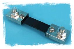

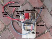
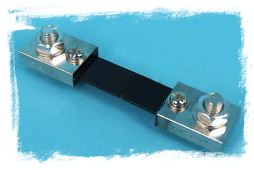
The power distribution board is located next to the battery. A 100A shunt for the multi-function panel meter is in the negative line and a 200A ANL fuse is in the positive line.
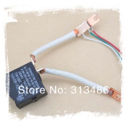
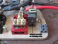
Low Voltage Cut is made using a 100A latching relay – a brief 12V pulse to the relay cuts all power except to the 1500W inverter. Manual reset is required and the actuator is shown in one of the main photographs. Note that the relay advertised is not quite the same as the one I was supplied with.
At the top of the board are two Clipsal L4T35 terminal blocks for the distribution of power to the Elektroblock, the trunk cable to the front of the campervan, the 300W inverter over the stove, and the control wires for the D+ signal from the alternator. Cables for the shunt for the multi-function panel meter and for the voltage sense for the solar controller also go to the board.

Delay Board with HVC and LVC
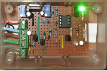
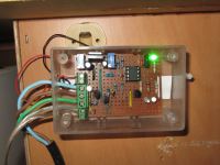
The delay board uses a microcontroller (an ATTiny85) and a few transistors and LEDs. It is built on Veroboard.
The circuit for the board is described next.
When the Junsi alarm activates, it sets TRIG LOW. This is read by the ATTiny85 micro-controller which also reads the battery voltage at (R). The voltage presented to the micro-controller is scaled by 1/3 by the potentiometer there and is compared to the cut-point voltage of 13V. If the voltage is greater than 13V then the alarm must be a HVC. If the voltage is less than 13V the alarm must be a LVC.

The micro-controller, having decided which alarm has gone off, sets PB0 HIGH (LVC) for one second to pulse the NC latching relay, a 12V relay, OFF, or sets PB1 HIGH (HVC) for a 'delay' interval to provide power to the NC 12 V relays that cut off all charging sources.
For a HVC the time that the relays are powered is the 'delay', and this is read from the potentiometer at (D) as a voltage in the range 0..5V which is interpreted as a delay of 0..10 minutes. (I set it to what I thought was 3 minutes, but it turns out to be about 4 minutes and I haven't bothered to change it.) This delay can be changed at any time without cycling the power to the circuit. This is, I believe, a desirable feature.
The LVC latching relay needs to be manually reset once the battery voltage is in the safe range. This is, I believe, a desirable feature.
The slight complexity in the output circuit is due to the three HVC relays in the Elektroblock being grounded, rather than floating. They are normally unpowered (NC) so minimising standby current.
The code for the ATTiny85 was prepared in the Arduino Integrated Development Environment and was burnt into the microcontroller using a Tiny AVR Programmer from SparkFun Electronics. The code is available here as a text file.
A note on reading the analog and digital inputs: both are read five times, waiting 50 mS between readings to avoid false readings. The digital readings are ANDed together so an alarm trigger must be true for all five readings. The five analog readings are averaged and the result compared to the cut-point voltage. The result is that the inputs are fairly well protected against noise and false readings.
Troubleshooting
Something may fail, probably a broken wire, connector or relay. To track this down, one way is to test the operation of the delay board.
Disconnect the solar input to its controller, otherwise it may confuse the investigation. Remove Block 4 Connector from the Elektroblock, remove the microcontroller from its socket on the delay board and restore Block 4 Connector.
Then the voltages on the microcontroller socket can be read: pin 8 is Vcc (5.0 V), pin 2 is the HV/LV Cut setting (~4.33 V), pin 7 is delay time set (~1.5–2.5 V).
Momentarily joining pin 8 and pin 6 should cause the blue LEDs on the board to flash and the relays in the Elektroblock to click on, cutting all charge current to the battery. Momentarily joining pin 8 and pin 5 should cause the white LED on the board to flash and the LVC relay to trip off, cutting power to all loads except the 1500 W inverter.
To restore operation, again remove Block 4 Connector, replace the microcontroller and replace Block 4 Connector. Manually reset the LVC relay. Restore the solar input to its controller.
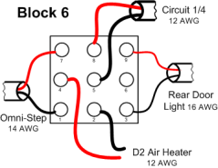
Block 6 on the Elektroblock
Initially not used at all, Block 6 is now very busy. The Eberspächer diesel blown-air heater is connected to Pins 4 and 2; the Omni-Step is connected to Pins 7 and 1; the rear door light (activated by opening the back door) is connected to Pins 9 and 3; and Circuit 1/4 (used at present only to supply the cabinet light under the cooktop) is connected to Pins 8 and 5.
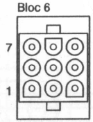
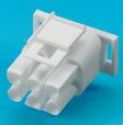
The Block 6 9-pin receptacle on the Elektroblock is labelled as an "MNL socket cap 9x" and is polarised in a particular way, as shown here. A matching plug is TE CONNECTIVITY/AMP 35072-1, a nine-contact housing. Suitable pins are TE CONNECTIVITY/AMP 926900-1, crimp brass pins for 16–13 AWG wire.
The pins and contact housing are available from element14 (formerly Farnell).
Monitoring house battery Current
The present meter is discussed here. Much of the following is for historical interest only.
Monitoring the house battery current consumption gives a check on operation
of the motorhome electrics. The Elektroblock EBL 269 has a built-in 1 mV/A shunt
accessible from the LT400 Control and Switch Panel. A monitor using that shunt
will also show the charging current when the van is plugged in to 240 V power.
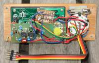
I have built four versions of the current meter (
 ). Versions 1–3 use
the Elektroblock shunt, and Version 4 adds a current shunt at the battery so that the
total current input to the battery can be monitored.
Current Meter v1
Dick Smith Electronics DSE Q2220 3½ Digit LCD Voltmeter Module is a 200 mV fsd voltmeter. So it will give a direct reading of Amps when connected across the EBL 269 shunt. The meter only draws 1 mA, so the simplest way to power the meter is to use a 9 V battery as follows:

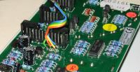
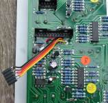
Four-colour ribbon cable to the LT400 Control and Switch Panel is soldered there to points near the main plug connector. There are pads for the current shunt on the circuit board (Pin 1 (yellow) and Pin 4 (orange) near the connector). Since analog voltages for the House Battery (Pin 4) (orange) and Starter Battery (Pin 8) (green) with Common negative at Pin 2 )(blue) are available there too (see the EBL269 circuit diagram), these are made accessible as touch points on the meter box front for reading with a multimeter.
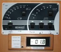
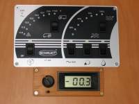
Installed in a wooden box, a photo of the meter is shown with it reading 1.8A consumption (negative current) due to two 10W halogen lights (1.7A) and the LT400 itself (~0.1A). The battery voltage touch points and ammeter power switch are on the left of the meter module. The meter box is attached to the wall by two keyholes in the back, and sliding to the left over countersink-head wood screws.
Current Meter v2
Alternatively, when it is powered from the same battery as it monitors for current, this kind of meter requires a dual power supply with common-mode input voltage well between the supply voltages. An attempt to implement this was made with the general idea as follows:

The negative supply is easily provided, using a 7905 to provide -5V relative to voltage (1), the Load. A positive supply relative to voltage (1), the Load, requires addition of a voltage pump. One was made based on an NE555 IC running as an astable, the output of which was rectified to pump up a capacitor to a positive voltage. While this worked, there was a non-zero reading when the inputs were shorted: this could not be resolved for quite a while. It turns out that I had made a fundamental error of precision metering, namely the meter was drawing current from one of the sensor wires and the impedance of that wire is sufficient to cause a voltage drop of a couple of millivolts - the observed offset.
Current Meter v4
While puzzling over why v2 did not work, I came across kit K212 from
Oatley Electronics, a $9.00 panel meter interface
kit that is designed to allow the kind of digital panel meter I am using to measure its own supply
voltage.

The kit bolts onto the back of their DPM1 panel meter (cheaper than DSE's) so I bought one of these too. The new circuit uses the kit's DC to DC power supply, the on-board variable resistor set for battery voltage measurement, and a 4-pole 3-position break-before-make rotary switch (DSE P7520) to give readings of consumer current (from the LT400 current shunt pads), using the current shunt added during the rewiring of the house battery for the State of Charge monitor gives total house battery current, and house battery voltage. A 500mA fuse and small slider switch are added. Five-strand ribbon cable is used to connect the circuit to the LT400, and a separate cable connects to the battery shunt.
The DC to DC power supply circuit is:

and the selector switch wiring is:
.png)
The selector switch gives:
- Current consumption via Elektroblock (-ve)
- Total current input to house battery (+ve)
- Voltage of house battery.
Notes:
- Since realising that the power to supply the meter should not be obtained from a shunt lead (because any voltage drop is seen as an offset on the meter), I use Pin 11 on the LT400 connector, the Battery Sensor (red ribbon), as the 12 volt input to the DC to DC supply.
- The floating DC output from the DC to DC supply had a lot of common mode noise, including 455 kHz stuff from the IF transformers on the board. This is largely removed by adding a 0.1 µF capacitor to ground the output with respect to AC.
- Using an oscilloscope I also found a lot of noise on the wiring from the Elektroblock, especially on the shunt leads. So I have added an inline filter to the inputs to the panel meter from the rotary switch (wipers A and B).
- The third set of contacts on the rotary switch (C and 7, 8, 9) switch an adjustable voltage divider across the terminals of the batteries to bring the voltage into the range of the panel meter (0-199.9 mV)
- The fourth set of contacts on the rotary switch (D and 10, 11, 12) is used to switch the decimal point on the display for battery current (0-199.9 A) and battery voltage (0-19.99 V)
- The inline 500 mA fuse proved essential: I blew it three times during testing when I slipped with test probes.
Multi-Function Panel Meter
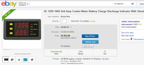
Dec2013: The current meter has been replaced by a multi-function panel meter from "Elite-Element", model DCM-120100C. This meter comes with a 100 A 75 mV shunt and connector board. It measures and displays battery voltage, time on, current, Ah, %charge, and whether the battery is being discharged or charged. There is a fair bit of instability in low current readings and these do not appear to be very accurate, but overall it is a nice piece of equipment.
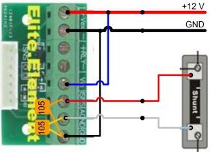
The connector board includes a circuit to switch on a relay at a set state-of-charge, but this
is not implemented in the meter itself (other models do this).
Note that "Vext-" and "GND" are joined on the board, but I also have linked them. I have also added
0.1 µF bypass capacitors between GND and each side of the shunt connections to reduce noise
that may have caused a failure in the first of these meters that I had. The existing plugs on the
display board used to power earlier versions of the current meter are used for the panel meter.
"Vin" and "Vext+" are joined and connected to the red wire (11), and "GND" is connected to the
black wire (2) in the connector to the Elektroblock panel. The red and white wires from the
battery shunt on the power board connect to "ISNS" and "AGND" such that when the battery is
charging, the charge indicator on the meter lights.
Documentation can be found here for the wiring of the meter and for the setup and calibration of the various functions.
Monitoring Status of Roof Equipment
I have added a panel below the current meter with a set of LED lights and switch to give the status of the TV antenna (whether up or down), of the deployable solar panel (whether out or packed), and whether the shower room hatch and the main skylight are closed. Half the panel is blank, awaiting new ideas.
The TV antenna has a new tilt switch ( Jaycar #SM1035) added and the cable for this is fed down the kitchen rangehood vent pipe to the monitoring panel. The deployable solar panel has a pin switch ( Jaycar #LE8777) located on one side that opens when the panel is latched down for travel. Its cable also feeds down the rangehood vent pipe to the monitoring panel. And the two roof vents (hatch and skylight) each have a magnet attached that closes a reed switch (Altronics #S5154B) when the vent is closed. These two switches are in series, so both vents have to be closed for the indicator on the monitoring panel to show ready for travel (green).

A bipolar LED ( Jaycar #ZD0248) is used to display green or red. Each LED is driven by two of the four Op Amps in each of two LM324 packages ( Jaycar #ZL3324). The LM324's differential input voltage range can be the full power supply voltage, so there is no need to include resistors on the inputs. There is also no need for controlled hysterisis on the positive feedback from one Op Amp to the other, since the control signal is a simple switch.
The circuit works as follows: with the switch open (e.g., TV antenna parked) input pin 2 is high so output pin 1 is low compared to the mid voltage at input pin 3. So input pin 6 is low and thus output pin 7 is high and the green LED lights. When the switch is closed (the antenna is up) input pin 2 is low so output pin 1 is high, input pin 6 is high and output pin 7 is low and the red LED lights. Power consumption is ~18.3 mA green, 19.0 mA red. Only one circuit includes the divider string of resistors. All others use that mid voltage reference. And the circuit for the roof vents has the LED reversed since the switch is closed when the vents are closed. The fourth circuit and LED are unused so far.

 The panel switch is very similar to those on the Schaudt LT400
control panel, and is a modified mini-SPDT centre-off spring return both sides
(
Jaycar #SK0987). The rocker markings have been removed using Brasso, and the spring and bridge
have been removed from one side of the mechanism to make the switch a spring return one side, latching
action the other side.
LINKS
- A'van http://www.avan.com.au
- Schaudt Systems http://www.schaudt-gmbh.de
- SparkFun Electronics http://www.sparkfun.com
- element14 http://au.element14.com
- Dick Smith Electronics http://www.dse.com.au
- Oatley Electronics http://secure.oatleyelectronics.com
- Jaycar Electronics http://www.jaycar.com.au
- Altronics http://www.altronics.com.au
12V Electrics
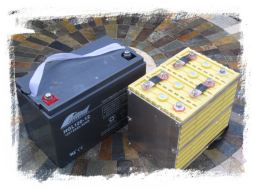
Comparing 100 Ah LiFeYPO4 (right) and 120 Ah AGM (left) batteries.
A later version of the monitoring panel. The monitoring Cell-Log is installed, showing the effect of powering an 850 W microwave oven.
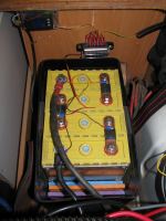
Lithium battery installed. The alarm Junsi Cell-Log is on the rear wall with its control box, as is the multi-fuse connector block. Each cell is monitored.
The battery board with 200A fuse, 100A shunt & 100A latching relay for Low Voltage Cut.
Top view of the battery board showing the manual reset for the latching relay.
Control box installed on the rear wall of the battery compartment. Green light says circuit is operating.
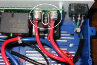
The EBL 269 elektroblock current shunt.
Version 1 wiring of Control Panel to access current shunt and battery voltages information for Applause
Version 1 Current Meter mounted below Control Panel for Applause electrics
Version 3 wiring of Control Panel to access current shunt and battery voltages information for Applause
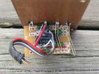
Back of Version 3 Current Meter: DC-DC isolator, meter input filter, voltage divider, and 4 pole 3 position rotary switch.
Version 3, 4 Current Meter below LT400 panel.
Circuit board for TV antenna and solar panel monitoring. The two bipolar LEDs on the right are not yet used.
The partly-populated lowest panel indicates the travel status of the TV antenna, solar panel and the two skylights on the roof. A version of the current/volt meter is above.
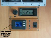
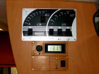
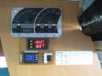
Final Montoring Panel. Below the Elektroblock LT 400 panel is the multi-function panel meter showing voltage (12.52 V) and charging current (16.9 A). Below that is the Junsi battery pack and cell monitor, and the stowage status lights.
