Adding a State of Charge Monitor
Dec 2013: Most of the description here is out of date with the fitting of a lithium battery. It is retained for historical interest.
Since the fridge is on-line in the Applause all the time, measuring the at-rest battery voltage to estimate the energy state of the house battery is not really possible. A State of Charge monitor measures the current to the battery and integrates this over time to give a running total in terms of Amp-hours as the battery is charged and discharged. This gives a far more accurate picture of energy stored in the battery. Expressed as a percentage, a full battery reads 100%; we try not to go below 70%, and if the battery state of charge goes below 50%, damage will have been done.
Available SOC Monitors
Several of the more expensive Solar Power Managers (e.g., Plasmatronics) include a State of Charge or Energy State function.
Silicon Chip described a "Battery Capacity Meter Circuit" in the June 1998 issue. No kit was ever made available, and the circuit used now out of date components and was unduely cumbersome though it was, for its time, quite advanced in using a PIC programmable microcontroller monitoring the amplified voltage drop across a current shunt.
 It seems that Hall-effect sensors have now
developed to the point where they are stable enough to use routinely to measure current
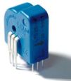
in challenging conditions. The LEM
LTS 25-NP is one such, and it is combined with a PICAXE in a
kit from MTM Scientific, Inc. It is this
US$59.00 kit that I have built and installed in the Applause.
 Elektor Magazine for
June/August 2008 (Issue 379) describes (pp24–5) a Battery Discharge Meter based on
two PICs and an
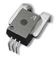
Allegro Microsystems Inc ACS750SCA-050 Hall-effect sensor. The sensor is available
direct in demo board form for US$20.00. Unlike the LEM version, it has the sensing wire
built in: this would have been more convenient for my application.
The MTM Scientific Battery Amp-Hour Meter
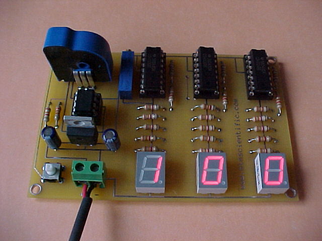
The supplied kit consists of all components and a double-sided circuit board and went together easily. A ten-turn potentiometer is used to set the battery A-hr capacity, which is displayed at power-up for 60 s. I found that at first the display counted up rapidly, uncontrollably. Adjusting the potentiometer over a broad range made no difference. It was only when I set the potentiometer fully anticlockwise that the circuit performed correctly. I was then able to set it to the correct battery capacity (The present battery rating is 120 A-hr). After a minute, the display shows percentage capacity remaining, between 0 and 100%. Current consumption is 40 mA.
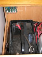
For the present application the Hall-effect sensor is mounted remotely, close to the battery, and the main circuit board is mounted on the wall behind the battery, on the wall shared with the gas bottle compartment. The LTS 25-NP sensor has a 3 mm diameter hole through which the current carrying wire passes. I use a short length of 10 AWG (4.9 mm²) wire for this task. A four-colour ribbon cable joins the sensor and the main board, and 0.1 µF noise suppression capacitors are mounted on the sensor sub-board: between the +12 V supply for the main board and ground, and between the +5 V supply to the sensor and ground.
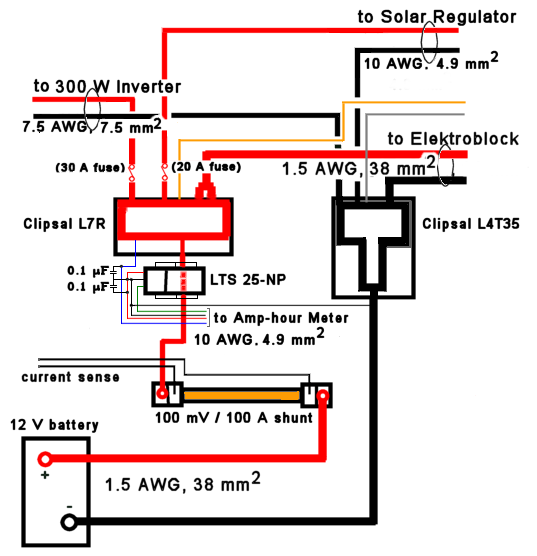
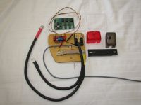
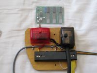
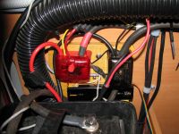
The diagram shows the changes I have made to the wiring to the house battery to include the LTS 25-NP Hall-effect sensor. At the same time I also included a new 100 mV/100 A current shunt (from The 12 V Shop, though I have since discovered that Jaycar sell an inferior product at a third the price). Photographs show the components on their mount board, the board with the covers on, and the Amp-Hour Meter in position.
Monitoring State of Charge
Starting up: as stated in the instructions, it is important that no current flows through the current sensor during the first minute of operation. The PICAXE uses the first minute to determine what sensor output voltage corresponds to zero current flow; if there is any current it will be interpreted as a voltage offset, and later current flows will be erroneously measured. This means that nothing else can be connected to the battery when the Amp-Hour Meter is started - a nuisance that is easily dealt with by powering the meter from the second sense point on the current shunt. Then I can simply disconnect and connect the terminal block to the shunt.
In service: Since the meter will not read over 100% battery capacity, there is no need to be concerned about the initial reading of battery state - it will by either the mains charger or the solar panels, at some stage reach 100% charge. From then on the meter should read the present state of charge, resetting itself each time 100% charge is achieved. So long as the 100% stage occurs for long enough then the battery will truely reach full charge. (Since internal resistances must be overcome, full charge of the battery will actually take longer to achieve, perhaps 10% longer than when the meter says.)
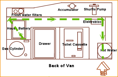
Along with the house battery, the meter is located under the foot of the bed at the back kerbside. Its readings can be viewed by raising the bed, and opening the hatch to the battery compartment. More convenient is to read the meter from the the roadside rear access door to the hot water service and solar panel regulator, where the performance of the solar panels can also be consulted. This is achieved by locating two mirrors so they reflect the meter display. The diagram makes this clearer, and some photos show what can be seen from that door.
The lowest State of Charge observed so far is 64% — i.e., Depth of Discharge 36%.
Reliability of State of Charge Reading
The PICAXE algorithm is fairly simple. As already mentioned, it does not recognise that charging the battery requires more energy than can be withdrawn due to losses — charging losses of more than 10% are common. Nor does the algorithm attempt to compensate for charge and discharge temperatures, which affect the energy that can be withdrawn. Nor that the energy available from a battery varies according to how rapidly it is discharged (and charged) — Peukert's Law. Nor that the battery capacity reduces with age.
Very few State of Charge meters account for all of these effects. In normal operation (i.e., not when the whole system is at idle for days or more) we can mitigate most of these issues:
- ensure that readings are only considered if indicated full charge has been maintained for at least an hour or so within the last 2–3 days;
- the battery is within the house, and temperatures there are unlikely to vary greatly due to human comfort factors;
- The rated capacity of the Fullriver HGL battery, the C20 value, is 6 Amp for 20 hours, the battery is near-new, self-discharge is very small at 0.7% per week, and the Peukert exponent for normal current draw in the Applause (1–20 Amp) is particularly low at 1.133.
In practice in the Applause the current draw is mostly below the C20 value of 6 Amp, so the Peukert effect error is likely to be quite small (it would be zero for 6 Amp draw). Combinations of fridge and water pump or vacuum toilet pump are active for only seconds at a time. But with TV and lights on for an hour or more the current can be 7–8 Amp for the time the fridge is on, reaching 15–20 Amp when the water pump is also on. I expect the error will to lead to a slight underestimate of the indicated State of Charge: a useful safety effect.
LINKS
- MTM Scientific http://www.mtmscientific.com
- The 12V Shop http://www.12volt.com.au
- Fridge-and-Solar http://www.fridge-and-solar.net
State of Charge wiring
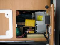
New battery power board with Hall-effect sensor and current shunt and remote State of Charge Meter; covers off.
Closeup of the power board and the remote SOC Meter. Covers are on the current shunt, terminal blocks and SOC Meter.
Battery in its box with new wiring. SOC Meter is on the back wall displaying 100% charge.
Battery power board mounted on the wall with cables connected.
View of rear compartment with hot water service, solar regulator on door.
View of rear compartment with hot water service. SOC display is visible.
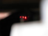
View of rear compartment, close up showing SOC display of 75% charged.
