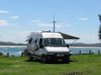
TV antenna modifications
The AntennaTek TV antenna
The TV antenna supplied with the Applause is an AntennaTek Model 500 12 V amplified double-dipole directional antenna, controlled from within the van. This is a Winegard RV3095 Sensar III clone with slightly higher amplifier gain.

- Amplifier Gain: VHF-16.5 dB UHF-21.0 dB
- Power Req.: 80 mA @ 12 V
- Impedance: 75 ohm
- Height lowered: 100 mm
- Heigh raised: 1000 mm.
Note that some parts are interchangeable between the AntennaTek and the Winegard. The windup handle is one, even though it is a slightly different shape.
Horizontal and Vertical Polarised TV Transmissions
While this is an excellent antenna, well suited to the Applause, it is only capable of receiving horizontally polarised signals. In Australia, a large number of regional stations transmit vertically (or even cross-) polarised signals. This is mentioned by ACMA in a discussion of transmitters in Australia. The Winegard does not do well with these, though there is usually enough spillover to see something.
I have prepared CSV files of Analog and Digital TV transmitter sites for Australia using ACMA data, showing whether the signal is horizontally or vertically polarised. The files are suitable for loading directly into my Garmin 250W GPS as POI files. They can be converted easily to other formats. The CSV files and related Icon files can be downloaded as a ZIP file. Each transmitter location starts with H or V (and a few M, etc) indicating the polarisation. Although there are often several transmitters at a site, only one name is given, though several sites have both horizontal and vertical polarised transmissions so these sites appear twice. Several cases have transmitter sites as close as 50 m and these are included. There is also an indication of the power of the transmitter at each site.
Modifying the Antenna for Vertical Polarisation
This modification builds on ideas originally posted on a forum by David Nye some years ago.
The AntennaTek antenna is extended remotely by a pantograph arrangement made from two 25 mm square aluminium tubes. The extended antenna can be tilted to the vertical quite easily by detaching at its lower end, the square support tube that does NOT carry the TV cable, and pushing it upward. 60 mm of movement turns the antenna head from horizontal to vertical. Little force is required as the antenna is well balanced.
The modification cuts this support tube about two thirds up from the bottom and inserts a 300 mm long stick of Merbou, 20 mm square. The Merbou stick is pinned to the upper part of the tube, and the lower part of the tube slides freely up and down the stick. The stick is grooved to allow water to drain down the tube. I use Merbou rather than aluminium to reduce the possibility of binding as the stick ages.
A sheathed cable, clamped to the lower part and pinned to the upper part, joins the two parts of the tube. With the cable fully retracted, the antenna will deploy normally, ie horizontal. But if the cable is then extended 60 mm, the antenna turns to a vertical orientation.
A 3 metre long 30 Series Positive Lock Cable from Teleflex seems a good (but expensive) choice for the sheathed cable. It is available with a clamp end, has a solid stainless steel core, and can be locked retracted or extended with a small twist of the extender handle. It is very robust and should work well when exposed to the weather. Teleflex sells direct, with length made to order. I bought a 043151-3-0300 for $117.65 delivered.
I clamped the Positive Lock Cable to the lower tube with two 30 mm stainless steel hose clamps (the type with stainless steel worm). I pinned the inner cable to the upper tube by a cross-plate screwed into the tube and inner Merbou stick. The extender handle was mounted horizontally on a bracket screwed into the rear solar panel surround so that it is accessible through the opened central skylight.
By the way, the pivot pins for the pantograph arrangement were retained in position with cap nuts. These are horrid little devices that are hard to reuse. I replaced them with "E" clips after turning a groove near the end of the pins to accept them.
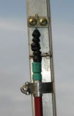 The photographs should make this description clear.
The modification operates well: the antenna mechanism is not restricted by the clamped cable and has full movement, the extender handle is easily operated and locks securely, and the antenna changes smoothly between horizontal and vertical orientation.
The addition of a (neoprene?) rubber boot from a mountain bike brake cable to the actuating cable to reduce ingress of dust and water completes the installation. The photo shows it above the green shrink tubing below the cable clamp.
The first real test I have managed was at Port Augusta where the ABC transmits on vertical polarised signal and Channels 10 and 7 are on horizontal polarisation. ABC could be received with the antenna horizontal but the signal was substantially noisier than when vertical.
A visit to Dangelong Nature Reserve, south east of Cooma (NSW) provided another test. The analog transmissions available there are vertically polarised. The left picture shows reception with the Winegard oriented horizontally, the right picture for vertical orientation.


A Tilt Switch on the Antenna

A mini mercury switch, Jaycar #SM1044 is installed on one support tube so that it is open circuit when the antenna is wound down to its parked horizontal position. As the antenna is wound up, the switch tilts and goes closed circuit. This signal is sent to the house control panel, as discussed on the page dealing with 12 V electrics.
Servicing the AntennaTek Assembly

Not a modification, but an amplification of the instructions for lubricating the Winegard Assembly
The elevating gear [Part 5] and the bearing surface between the rotating gear housing [Part 7] and the base plate [Part 8] needs to be liberally lubricated every six months with silicone spray.
As does the rubber quad ring (looks like an "o" ring) on the elevating shaft [Part 6] which is below the worm gear. This keeps the quad ring from becoming brittle which could then result in water leaking down the elevating shaft.
Step 1: Lower antenna to travel position. Loosen set screw on elevating crank, remove
crank [Part 12], spring [Part 10] and directional handle [Part 9].
Step 2: On the roof, remove top retaining ring from top pin holding top elevating tube
[Part 2] in rotating gear housing [Part 7] and remove pin.
Step 3: Remove plastic plug from top of rotating gear housing, disengage elevating gear
[Part 5], remove elevating shaft assembly [Part 6] by pulling it upward.
Step 4: Lubricate worm gear and quad ring, on the elevating shaft assembly [Part 6] with
silicone spray lubricant, and insert assembly in housing.
Step 5: Reinstall plastic plug in top of housing. Reinstall top elevating tube and pin.
Gears will mesh automatically once elevating crank is turned.
Step 6: Replace directional handle, spring and elevating crank. Make sure set screw contacts flat
surface on shaft before tightening.
Directional Elements for the AntennaTek
Its possible to buy an add-on for the Winegard, called the Wingman than improves signal strength by about 3 dB in the UHF range. There is even a version modified for the A-NZ market, having slightly shorter elements to increase the centre frequency to better match the overall higher frequency range of Band V used here: there are a lot of regional stations using channels 60–69 ie., frequencies as high as 814 MHz. AntennaTek has claimed that their antenna does not need such an addon, but that does not disuade me from proceeding.
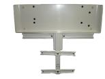
Using a discarded UHF TV antenna, I made my own add-on. As can be seen from a picture of the Wingman, it consists of three elements that clip in front of the antenna head. The two front elements on the US version are 175 mm long and the rear element is 350 mm long. On the A-NZ version, they are 140 mm and 300 mm respectively. The elements are quite chunky, causing a broadening of the signal bandwidth at the expense of gain.
The UHF antenna I had had a section that was quite close in dimensions to the US Wingman. The difference to the A-NZ dimensions should make little difference because the required bandwidth is quite broad and the antenna elements are also similarly chunky to the Wingman. I cut the antenna so that it has two front elements 178 mm long and the rear element (in two parts, isolated) is 350 mm long. The elements are 114 mm apart (centre-centre).
The resonant frequency of an element is given by the formula
For L = 350 mm, f = 367 MHz, and for L = 178 mm, f = 722 MHz. The latter value seems appropriate for Australian UHF frequencies which range from 529.5 MHz (Band IV, Ch 28) to 816.5 MHz (Band V, Ch 69). Presumably the resonant frequency for the longer element is chosen to give coupling to the shorter of the double dipole (very much like the Matchmaster G-Unit) in the main AntennaTek antenna.
The extension is simply bolted to the front of the AntennaTek head through the plastic with two brass bolts and nuts. A pad on the roof of the van provides a support when the antenna is fully wound down.
Performance
This is notoriously difficult to quantify. Recently at one remote spot, another camper noted we had TV and said "Oh, we've got nothing."
NextG antenna on the AntennaTek for Internet
On the road, mobile phone reception is important, and only Telstra has the coverage that suits us in our travels off the main routes. With a reasonable signal, fast internet access is a bonus using a browsing pack for the mobile. A blue-tick Telstra mobile with an antenna port permits much better coverage in out-of-the-way places using an external antenna, and the AntennaTek provides an ideal place to mount such an antenna — high above the Applause.
I bought a 7 dBi 850 MHz Next G omni antenna from City Technology to mount at the top of the antenna pantograph using a simple bracket pop-riveted to one of the arms. The RG58/U signal cable was fed through a hole into the Technical Cupboard where it can plug into the Telstra Dave. I sealed the hole in the roof with a generous application of Fuller Toolbox polyurethane adhesive.
Performance
The NextG antenna increases performance by at least two bars in areas with weak signal strength. Camped at Pretty Beach in Murramarang National Park (NSW South Coast) we were the only van with mobile phone and internet reception.
LINKS
- A'van http://www.avan.com.au
- AntennaTek http://www.antennatek.com
- Winegard http://www.winegard.com
- Teleflex http://www.teleflex.com.au
- Telstra http://www.telstra.com.au
- City Technology http://www.citytechnology.com.au
Antenna Modifications
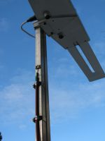
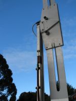
Modified AntennaTek antenna horizontal. The Teleflex actuating cable is clamped to the pantograph tube that is cut in half.
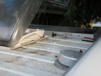
The extending handle for the actuating cable is mounted near the central skylight so it can be operated from within the van. Position for horizontal antenna.
Modified AntennaTek antenna vertical. The extended Teleflex actuating cable is visible, as is the guiding Merbou core for the upper tube part.
The extending handle is pushed in for vertical antenna. A slight twist locks it in position.
The antenna folds down onto the van roof easily. The red actuating cable and extending handle are visible.
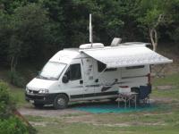
Camped out at Treachery Camp, Seal Rocks, on the NSW Central Coast, far from towns behind sand hills. The only TV signal was vertically polarised.
The AntennaTek antenna head with directional elements installed (Next G antenna behind).
The 7 dBi Next G antenna is mounted behind the AntennaTek with directors added.
The Next G antenna is mounted on the AntennaTek with a simple bracket.
Camped out at Point Plomer, 18 km south of Crescent Heads on the NSW Central Coast, with great TV and mobile phone broadband reception.
