Omni-Step Slide Out 400
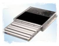
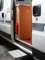
An Omni-Step slide out 400 step is fitted to the Applause, for the sliding door, and very nice it is too.
I found that the Aux switch on the Control Panel for the Elektroblock also switched the Omni-Step, but the Elektroblock is designed to independently manage the Step (see Elektroblock discussion).
As well as correcting this error, I decided to put in a circuit to automatically or optionally manually control the step retraction from the driver's seat. The Omni-Step Instructions include a circuit to do this automatically every time the ignition is turned on (see the Omni-Step Instructions and Circuits as PDF files - 1.33 MB each), but there may be occasions when we want the step to stay extended, even though the ignition switch is turned on to, for example, close a cab window. The supplied circuit has another undesirable feature: the power for the automatic retraction is supplied by the wiring to the ignition switch; this is as much as 14 Amp!
Rewiring Omni-Step Controller
New 14 AWG cables were run from Elektroblock Block 6, Pin 7 (+12 V) and Pin 1 (0 V) to the area at the back of the fridge compartment where the Omni-Step controller is located. This wiring is protected by a 20 Amp fuse labelled "Trittstufe" on the Elektroblock.
A schematic of the new wiring, based on but modified from the Omni-Step Circuits is shown here:

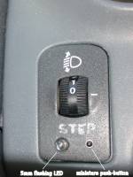
In this new design, the step motor is always powered by the house battery, over a single pair of power wires. A relay is introduced to be able to retract the step from the driver's seat if the ignition is on and the step is out. A flashing LED is mounted in the same instrument panel as the headlight beam level adjuster. A 2200 uF capacitor is wired across the relay to ensure the step is fully retracted.
In practice, I have found the remote manual control of the step to be more trouble than it is worth. I have bridged the push-button switch so the step retracts automatically each time the vehicle ignition is turned on.
Servicing the Omni-Step
Unbolting the Step box from the chassis gives full access to the Omni-Step since the cables are long enough to lay the Step on the ground. Then removing two bolts from the facia of the box allows the black plastic covers top and bottom to be slid out (after removing a large amount of accumulated dried mud and stones from the top cover).
The Step motor drives a pair of large aluminium gears and a smaller intermediate gear through a sealed gearbox. These large gears rotate scissor arms that retract and extend the step itself in the tracks on the sides of the Step box. A bit of grease on the gears, and on their shafts that protrude through the top of the box, is all that is necessary to keep everything in good condition.
LINKS
- Omnistor http://www.omnistorawnings.co.uk
- DSE http://www.dse.com.au
Slide Out Step
Omni-Step and Omni-Switch at Sliding Door. (Also visible are the fire safety blanket and hook for garbage bag, on the fridge cabinet with the Switch.)
The step remote control on the dashboard, fitted below the headlight adjuster.
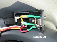
Wiring of the remote retractor controller on the dash.
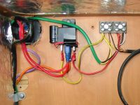
Wiring of the Omni-Step switch, relay and remote controller, at the back of the fridge compartment.
