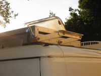
Solar Setup
The Initial Setup
As we bought it, the Applause had two 80 W BP solar panels mounted on the roof (see what's on the roof). They were regulated by an Electro branded, Manson-type, SBC-7120 solar controller, a 20 A regulator/controller with good display information. The panels were wired to the controller with 8 AWG (8.46 sq mm) multi-strand twin-pair copper wire, and the controller was wired directly to the house battery with 11.7 AWG multistrand twin-pair copper wire.
The SBC-7120 controller can display the total amp-hours to the battery for each of the last three days. On 9 Oct 2008, at 1330 EST at White Cliffs, NSW I observed a charging current of 9 A (voltage 13.9 V). The previous day, the energy input to the battery and consumers totalled 53.5 Ah.
- The 9 A implies a solar panel efficiency of 78%, rather better than the generally assumed 70%. (2 x 80 x efficiency / 13.9 = 9 A)
- The observed 53.5 Ah and 9 A peak implies a Sun-hrs value of 5.9, which is about
right for that district - climate data show
around 5.5–6.3.
(9 x Sun-hrs = 53.5 Ah)
Note that these performance figures may have been influenced by atmospheric dust in the region. This can in some circumstances enhance the solar input to ground by added reflections and reradiation. Such enhancement more commonly occurs when middle-level light cloud is present.
The SBC-7120 regulator has some strange behaviours. One is that if the battery is on float and the panels are in full sun and then a load is turned on (eg the fridge) taking a current that the panels could easily supply directly, the regulator does not switch on the panels. It waits till the battery voltage sags to ~12.6 V and THEN switches the panels on, going into Absorb charge mode for some time up to 14.3 V. So the battery is oscillating between 12.6 V and 14.3 V in bright sun as the fridge switches on and off. Why not let the battery float and just take the current from the panels?
The Manson controller manual says:
FLOAT CHARGE –The controller will maintain the battery voltage at the float voltage setting by giving shorter On-pulse charge to make up for any detected self discharge of the battery. When the battery voltage drops below the Float Voltage Setting for a total period of 10 minutes, a new charging cycle is activated in Bulk or Absorption Charge.
The problem is, when the battery is fully charged the unnecessary Absorption Charge current mainly drives electrolysis. Most of the gases recombine back to water, but some of the H2 escapes and some of the oxygen ends up in solid corrosion products. The battery dries out over time. The battery does not heat up noticably when this happens.
The behaviour seems OK for maintaining a battery in a no-load state, but does not work well for the motorhome application where a 12 V fridge is switching on and off all the time.
Winter bush camping experiences showed that we did not have enough solar power even on a good day. Nor enough battery capacity. While space in the Applause is at a premium, some things can be done to improve things.
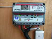
ProStar PS-15M Controller
I have replaced the SBC-7120 regulator with a MorningStar Prostar PS-15M from Watts2C.com.au. I had to return the first one received because the float voltage was well below spec.: 13.3 V at 25C instead of 13.7 V.
Features include:
- Rated charging/load current 15 A
- PWM Charging with 3-stage Charge Control (to allow battery be left unattended for long periods)
- Battery voltage sensing
- Battery temperature sense via fitted Remote Temperature Sensor
- Overcharge, Over-discharge and Over Temperature Protection
- Informative LCD Display and LED indicationw of system and battery conditions
The solar regulator output is fed to Block 3 of the Elektroblock, a two-pin socket protected by a 20 A fuse and originally designed for an external mains charger.
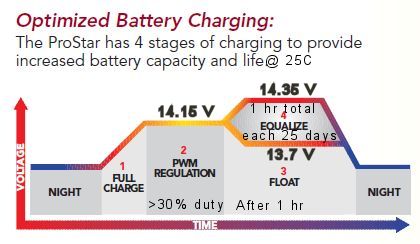
The diagram shows the charging regime for an AGM battery. For a Gel battery the PWM Regulation voltage is 14.0 V rather than 14.15 V and there is no equalisation phase. The ProStar consumes only 22 mA and can cope with a full 15 A and can handle 25% overloads, enough capacity to accommodate a third 80 W panel. The ProStar was connected to the house battery via a current shunt and Hall Effect Sensor, added to allow monitoring of the state of charge of the battery. Towards the end of an afternoon, using a calibrated multimeter I measured the regulator voltages as shown in the following diagram:

With 13.53 V across the battery as measured by the Sense Wires, the battery charge voltage was 13.65 V with a solar panel current of 3.4 A. Using other voltage measurements, I found that the voltage drop along the battery supply wires (~11.7 AWG) was 0.05 V, across the current shunt was 0.003 V and across the Hall Effect Sensor arrangement was 0.03 V. [These voltages were obtained from measuring the voltage between Charge + and Sense - of 13.60 V; and voltage between Sense + and Charge - of 13.57 V.]
Aug13: The ProStar is now connected to the Elektroblock at Block 3, repurposed for the task. The Hall Effect Sensor has been removed and a current shunt is in the negative line at the Lithium battery.

RTS for the ProStar
The ProStar monitors the temperature at the controller and adjusts the battery charge voltages accordingly. At -0.030 V/°C for a 12V battery (reference temperature 25°C) the charge voltage is reduced by 0.45V at 40°C. I have continued to mount the controller in the rear compartment next to the hot water service and that area does get rather warm after a while when the heater is used. To reduce the effect of the temperature difference to the battery, I enclosed the water heater with reflective insulating material from a front window shade and also fitted a Morningstar Remote Temperature Sensor (RTS). The RTS is recommended for a lead-acid battery
whenever the temperature at the battery will be more than 5°C different than the temperature at the controller.
The RTS was installed by soldering two wires (no polarisation) to the ProStar circuit board and bolting the power lug housing to the house battery negative terminal.
Using the Temperature Compensation in the Solar Controller

Dec13: When charging a Lithium battery the temperature correction in the ProStar is unnecessary and indeed unwanted. It cannot be eliminated from the ProStar but can be used to advantage by replacing the RTS with a suitable potentiometer.
This temperature compensation "feature" can be put to good use. I have measured the characteristics of the remote temperature sensor — it is a thermistor in a bolt-on metal jacket. I immersed the sensor in water at different temperatures and obtained the graph here.
Note in particular that at the reference temperature of 25°C the thermistor resistance is 10 kOhm. At this temperature the controller has setpoints of 14.0V for PWM Gel, 14.15V for PWM AGM and 13.7V for Float, though I think there is a fair bit of imprecision in practice.

Replacing the remote temperature sensor with a variable resistor and applying the temperature compensation corrections to the setpoint voltages, gives the graph here. So now we can dial up whatever PWM setpoint voltage we want. In particular, with the regulator on SEALED (AGM) setting, and the potentiometer set to 7.0 kOhm, the PWM setpoint is 13.95V, down from 14.1V. A possible problem is that the Float Voltage becomes 13.45V, down from 13.7V. This might be a bit low, but is probably fine, given that there is no need to maintain full charge for a Li battery.
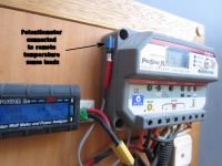
Jul14: The remote temperature sensor was removed and replaced with a 4.6 kOhm resistor and 10 kOhm multiturn potentiometer set to 3.4 kOhm (total 8.0 kOhm). This should set the PWM setpoint to 14.0 V. However, it does not seem to actually change the setpoint — I don't know what is going on.
ProStar Self-Diagnostics
The following protection functions and disconnect conditions are displayed on the ProStar when they occur:
Lud LVD – low voltage load disconnect (load only)
Hud high voltage disconnect (both solar and load)
Hot high temperature disconnect (both solar and load)
OCP overcurrent and short circuit protection (load, solar overcurrent)
0.0 short circuit protection (solar only)
The push button next to the digital display can disconnect the Load or both Load and Solar. A second push of the button will return the controller back to normal operation.
- LOAD OFF: A brief push of the button (less than 2 seconds) will disconnect the Load. The Solar remains on and charging.
- LOAD AND SOLAR OFF: If the button is held down for 2 seconds, the Solar will also be disconnected.
If the push button is held down for 4 seconds, the ProStar will go into automatic self-diagnostics. Note that the button must be released to start the self-test. The following displays will occur for two seconds each:
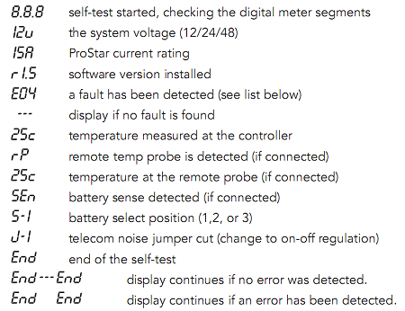
With the RTS installed, I used the self-diagnostics to compare the temperature of the house battery and the controller. On two occasions I have seen a difference of up to 4°C, and this was without the hot water service operating. So I surmise that fitting the RTS is a good idea for a lead-acid battery.
Three Solar Panels
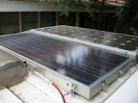
There is space on the roof to add a couple of small panels, but these would not add much capacity and would be subject to severe shading all too often. What was needed was a substantial addition. Having a set of folding panels is a way that suits some people, but I know I would rapidly tire of taking them off the bed, unpacking them and moving them around to follow the sun, as well as being concerned about their attractiveness to thieves. What if I could have a folding panel on the roof? But that would reduce the charging capacity to only one panel, the front one, if the rear one was not deployed. Or would it? If the "folding" panel merely slid from over the existing fixed one when deployed, I would always have at least two panels exposed to sunlight, and have three when the new one was deployed. Since they would be all the same size, this would give a 50% increase in charging capacity — well worth while.
I considered using full-extension ball bearing drawer slides (eg Hettich KA 5632) to extend a solar panel from over the rear BP panel to out over the back doors of the Ducato. However, I would need stainless steel slides and these are very expensive. They are also very complex, easily ruined by accretion of bull dust. The panel on the slides would have to be 30–50 mm above the fixed panel and so would likely shade it in some circumstances.
The alternative that I have employed is to use a simple mechanism to deploy a panel normally resting on the top of the rear panel while travelling. Two links, pivoted at the ends of the panels, would form the arms of a pantograph that could be designed to set the deployed panel almost flush with the existing panel. A precision engineering drawing of the arrangement that I have built is here:
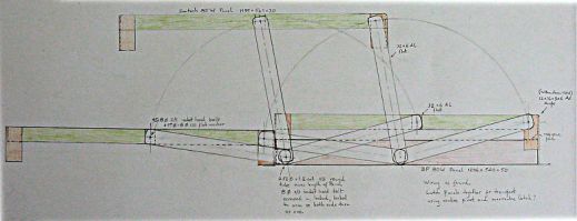
The 2 x BP 80 W panels, mounted on the roof are 1206 mm (+screw heads) x 540 mm (+bolt heads) x 50 mm. I initially thought of using another BP panel, but a Suntech STP085S-12/Bb 85 W panel came up at a good price; it is 1195 mm x 541 mm x 30 mm, which turns out to be a more convenient size than the BP panel upon which it sits since it becomes the same size when the 32 mm x 6 mm aluminium flats are screwed to its ends.
The lower rear pivot centre is 20 mm from the edge, as is the upper front pivot centre. The centre to centre distance of the arms forming the parallelogram is 231 mm and the arms are 278 mm long, centre to centre.
 The pivots are 40 x 8 mm dia stainless steel socket head
bolts, the shortest available which are not fully threaded. Three 15 mm dia x 8 mm dia stainless
steel washers are used to pack out each bolt to the right length for the threaded portion to engage
in threaded holes in the 6 mm flat screwed to the side of the Suntech panel. An 8 mm dia Nylock nut
locks each bolt in place. Lengths of 6 mm flat are also screwed to the inside sides of the BP panel,
and the pivots screw into that too, also locked in place with an 8 mm dia Nylock nut.
 The rear-most pivots in the BP panel are connected
together using a threaded length of 9.52 mm dia x 1.2 mm wall stainless steel pipe and lock nuts.
This provides some rigidity in the mechanism as it is deployed.
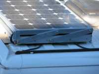
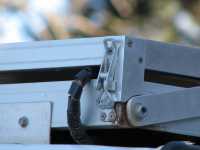
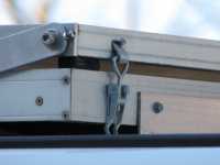
Blocks of sponge rubber (from shoe soles) are glued to the under corners of the Suntech panel and the panel rests on these when closed up. The panel is firmly located above the BP panel by right-angle arms that extend downward from the rear corners and mate with the corners of the fixed panel. These arms also are the mounting points for the over-centre latches used to lock the panels together while travelling. A slightly different, inverted, arrangement is used at the front of the panels — see the photos for how this was done. The result is that there are no obstructions on the BP panel that could potentially cause shading problems.
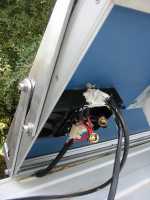
The lower fixed BP panel will be fully shaded much of the time, while ever the Suntech panel is locked in place. Some crude tests showed that in the dull conditions of the day, the BP panel would sink 0.08–0.2 A when shaded and the other panels are exposed. It seems prudent to put in a blocking diode for the shaded BP panel only. (I found on disassembly of the BP panel connection box that blocking diodes had been included for both BP panels. The conventional wisdom is that these are unnecessary.)

A pin switch, Jaycar #LE8777, is mounted on a bracket on the near-side of the lower fixed panel. It is closed circuit when the moving panel is set to its closed position, and is open circuit when the panel is deployed. This signal is sent to the house control panel, as discussed on the page dealing with 12 V electrics.
A later addition to the upper panel is a piece of 30 mm angle-section running between the two pivot bolts. This acts as a handle, assisting in deploying the panel from the roof hatch. One of the packing washers is now omitted.
A Test of the Panels
In the Flinders Ranges at Aroona, South Australia (31.28°S) on 22 March 2009 with all panels deployed, I observed a charging current of 12 A. With the cantilevered panel closed, the current dropped to 8 A. And with the front panel shaded, the current dropped to about 4 A.
LINKS
- A'van http://www.avan.com.au
- Watts2C http://www.watts2c.com.au
Solar System
ProStar solar controller on door of rear cabinet. Silver insulation covers the hot water service.
The ProStar controller displaying house battery voltage under charge.
A 10 kΩ potentiometer in series with 4.7 kΩ resistor takes the place of the remote temperature sensor on the ProStar solar controller.
Extending and retracting the extra solar panel.
Top panel locked down for travelling. The forward link arms have adjusters to fine-tune the articulation.
The power cable, overcentre latch holding the articulating panel down, angle used to locate the panel, and bull dust from Flinders Ranges.
Front pivot with adjuster screw, inverted over- centre latch holding the articulating panel down, and a sponge rubber block between the panels.
The connector block under the BP panel with its blocking diode. Heavy brass cable clamps join the heavy wiring. The pipe running between the rear-most pivots is visible at the bottom.
The articulated panel fully extended. In the foreground are the open panel latch, a pin switch used to warn that the panel is extended, and the red cable for the polarisation changer for the TV antenna.
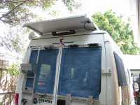
The extended solar panel shades the rear doors of the Applause. The power cable for the panel is neatly deployed.
A piece of angle-section has been added to make a handle for deploying the panel.

