Overview
The BEP Systems Monitor
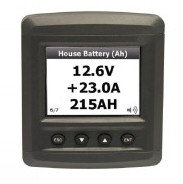 Systems Monitor has several displays. This one shows camper battery voltage,
charge current and state of charge.
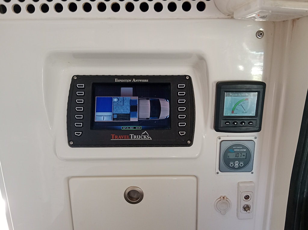
Systems Monitor is next to Touch Screen. Below that is a Solar Display though the Bluetooth app is easier to use.
The BEP Systems Monitor can report on the camper battery, including state of charge, the solar charging rate, and the starter battery voltage.
Alarms for the camper battery warn when the state of charge is low, when battery voltage
is low. THEY MUST NOT BE IGNORED .
Recharging must be commenced — start the engine with DC-DC charger selected so as to
limit the charging current to safe levels. The DC-DC charger will "wake up" the battery if
the battery is so flat as to be "asleep". See
Alternator Charging. Alternatively
use of the 15A 230V Mains Charger might
be possible, but this will likely take a lonnnng time.
In addition to the System Monitor, Victron provides mobile phone apps for the solar regulator and the 230V mains charger, and EV-Power supplies an app for the camper battery. These may be used to change the settings for the chargers. The configuration of the Victron inverter can be changed using a program running on a notebook computer plugged into the USB cable attached to the inverter.
Design for Wiring
New wiring was required to utilize the power of the 360Ah x 12V Lithium camper battery. The design maximum current is 300A, though 200A is the common maximum reached. With the newer drop-in lithium batteries the wiring has been changed again, to suit: it is simpler.
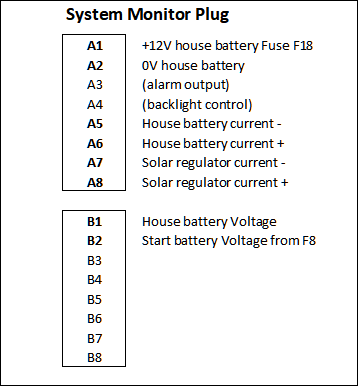
System Monitor detail
Current to/from the camper battery and from the solar charge controller are measured using two 450A 50mV fsd shunts (1mV = 9A) connected using shielded twisted pairs.
Cables from the Camper Battery
With a design maximum current of 300A from the the camper battery, we use 95 mm² cable for that task and for connections to the BEP monitoring shunt and the inverter.
- The winch supply front and back of vehicle is made in 70mm² cable. A negative cable from the battery goes onto the chassis rail to a common point, an insulated block with 1/2" UNC bolt and nut, with cables going to the front and back of the vehicle. The positive cable from the battery first goes to an isolating switch on the outside of the battery box and then crosses over to the other chassis rail to another common point, with cables going to front and back. So the winch supply does not go through the shunt and is unmonitored.
- A 50mm² positive cable goes directly to the cab, where it enters a BEP switch group for the starter battery and the camper battery, providing power in the cab and in the camper.
- The 95mm² negative cable goes from the camper battery to the 450A/50mV shunt for the BEP Systems Monitor. Since it is a major consumer it is important that the inverter's power consumption be measured by the Systems Monitor. So the cabling for the inverter had to include the main 450A shunt under the truck.
- There are four cables leaving the shunt:
- One 50mm² goes to the power distribution module in the camper.
- One 50mm² goes to the power distribution module in the cabin.
- One 50mm² goes to the chassis ground bolt on the rail behind the fuel tank.
- One 95mm² cable goes to the negative terminal on the Victron Inverter.
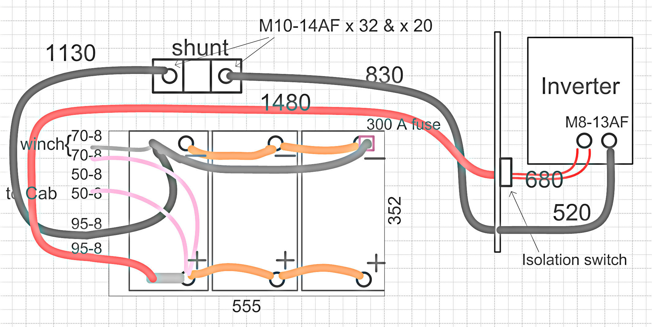
Batteries wired in parallel, cables for winch, power modules and inverter.
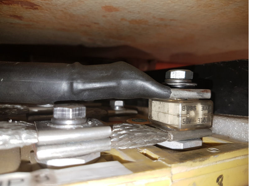
Shown for the earlier lithium battery, the 300 A fuse bolts directly to the battery terminal.
Note that the 95mm² positive cable is bolted to the nearest positive battery terminal via a short braided joiner because a longer length is required for the present battery configuration. Similarly for the 95mm² negative cable; it and the winch negative cable join a heavy link to the further-most negative battery terminal.
A Blue Sea 300A fuse is mounted on that negative terminal with a special acetal plastic top-hat washer that insulates the bolt from the cable lug. The fuse is a type of Marine Rated Battery Fuse (MRBF) with an Ampere Interrupt Capacity (AIC) of 10,000A @ 14 VDC. The result is that the camper battery is protected from a short-circuit for all loads by the fuse.
Cabling for the Inverter
The 3000VA Victron Phoenix inverter uses 95mm² cables for the DC supply. A first cables, lugs, 32mm dia. nylon glands, black and red heatshrink, and an overnight loan of a large hydraulic crimping machine, were obtained from an industrial electrical company, BDL. However, although flexible, the cable still proved to be too stiff and the route I chose for cables entering the camper body did not allow for the significant movement between camper and chassis. The cables tore the glands from the wall.
A fellow recommended welding cable for this job. Enquiries showed that short lengths of Transarc Superflex welding cable are available from BOC. A local agent was able to supply 3m of 95mm² cable as well as 2m of 50mm².
The end result is thus a mix of cables:
Lug crimped to the 95mm² BDL cable.
- A new 95mm² BDL negative cable replaces the 50mm² cable going from the battery to the shunt (lugs with M8 at battery, M10 at shunt).
- A new 95mm² BOC negative cable is added to the group at the shunt and goes via a vertical loop into the camper and to the negative plate in the inverter (lugs with M10 at shunt, M8 at inverter). The flexibility of the cable and the loop assures good behaviour with camper movement.
- A new 95mm² BOC positive cable goes from the battery via a vertical loop into the camper to an isolation switch (lugs with M8 at inverter, M10 at switch). Camper movement is accommodated.
- A twin 50mm² BOC cable goes from the isolation switch in the camper to the positive plate in the inverter (lugs with M10 at switch and M8 at inverter).
- A short length of 95mm² BDL cable makes a link between the further-most negative battery terminal and the negative cables leaving the battery box (lugs with M8 at both ends).
The twin cable was made up so as to give the necessary extra flexibility required in the camper and to allow a good connection to the pair of +12 V bolts in the Inverter.
DC connections to the Inverter.
Prepared 2 x 50 mm² BOC cables – isolation switch to inverter.
Prepared 95 mm² BOC cable – battery to isolation switch.
Assembly
All connector surfaces were deburred, scrubbed with steel wool and smeared with silver-based thermal paste from Jaycar.
Access to the shunt was a challenge. I had to obtain a longer M10 brass bolt for the load side of the shunt because of the extra lug for the 95mm² cable to the inverter. This bolt had a 15mm AF head, not 14mm AF like the original, so I filed it down but not very carefully and it suffered in the installation. A 14mm AF very fine ratchet spanner was necessary to tighten the bolt after much struggle to get it to line up with all four lugs on. The connection to the battery side of the shunt was relatively easy.
The isolating switch is a NARVA 61082BL Battery Master Switch rated at 300A continuous load.
The main 450A shunt is bolted to the passenger-side chassis rail. Access to the load-side connector is very restricted.
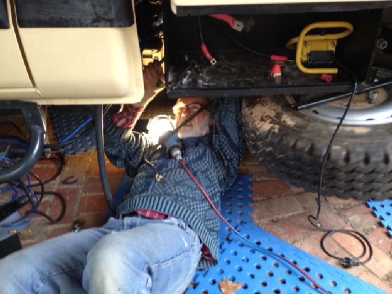
Peter attempting to assemble the load-side bolt onto the shunt.
A view of the main 450 A shunt with new 95 mm² cables connected.
Cables entering the camper.
32 mm dia. glands are used.
Cables leaving the battery box (cover off). The cables are UV stabilised.
Red DC cables to Isolation Switch and Inverter under the LH camper seat.
LINKS
