Inverter
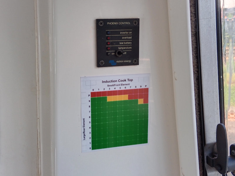
To run the 230V 2-element deLonghi induction cooktop we use a Victron Phoenix 12V 3000VA-2500W Inverter with a Phoenix remote control panel on the RH camper wall near the cooktop.

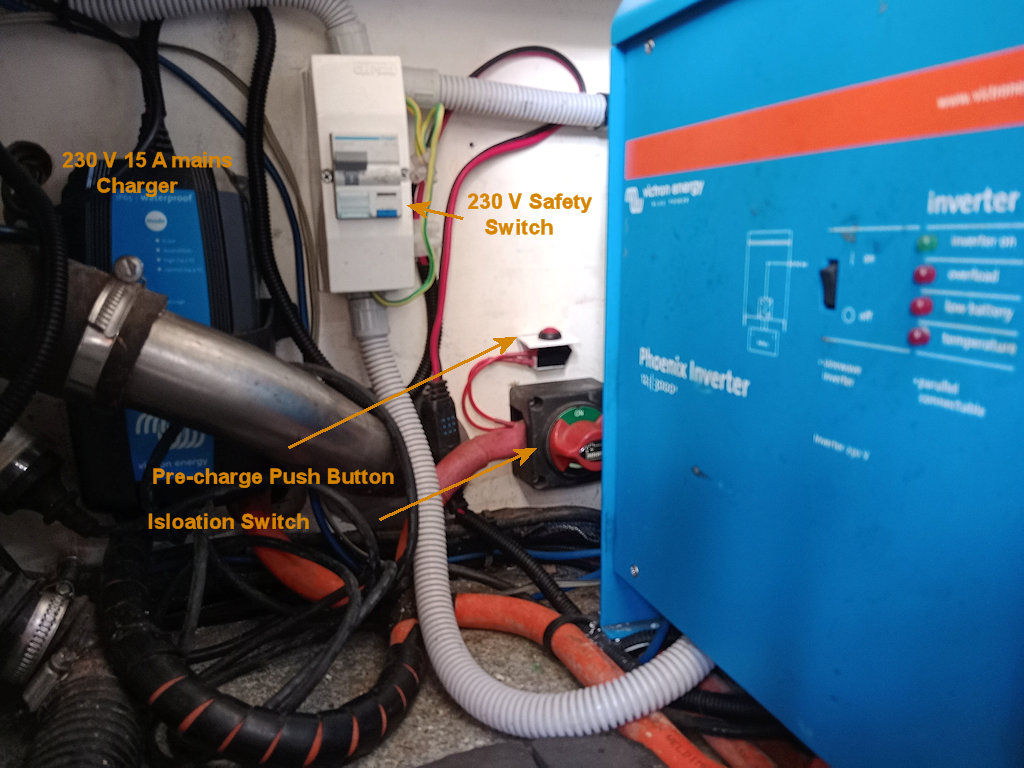
Victron Phoenix Inverter under the camper LH seat. An isolation switch and precharge press button are visible.

Phoenix remote control panel above guide for using cooktop elements.
From the user perspective there is often a slight delay in the starting of the 230V appliance being switched on when there is no other load on the inverter. This is due to the way power consumption is minimised when there is no load on the inverter.
The induction cooktop needs to be switched off at its isolation switch when not in use to allow the energy saving mode to operate.
The inverter is located under the camper LH seat. It is directly connected to the Camper Battery via its own isolation switch. Its a good idea to isolate the inverter when TT30 is not being used for a few weeks or more. Before switching the inverter back on with the isolation switch, press the push-button for a few seconds to precharge the capacitors in the inverter. Otherwise the very large inrush current when switching on will trip the safety circuits in the Camper Battery; if this happens, power will be restored in any case after a few minutes.
230V Supply
The installation of the 230V wiring was supervised by a qualified electrician and the completed job was issued with a Certificate of Compliance. All power points are protected by a residual current tripping Safety Switch.
Inverter Details
The DC cabling for the inverter supply is described in the DC Power Wiring page. Installation and operating instructions are here for reference. As per the instructions, the configuration of the inverter can be changed using a Victron program called VEConfigure running on a notebook computer plugged into the USB cable attached to side of the inverter.
The inverter has been configured to run in Search Mode so power-consumption in no-load operation is decreased by approx. 70%. In this mode the main part of the inverter is switched off in case of no load or very low load, and switches on every two seconds for a short period. If the output current exceeds a set level, the inverter will continue to operate; if not, the inverter will shut down again. VEConfigure has been used to set the “shut down” and “remain on” load levels.
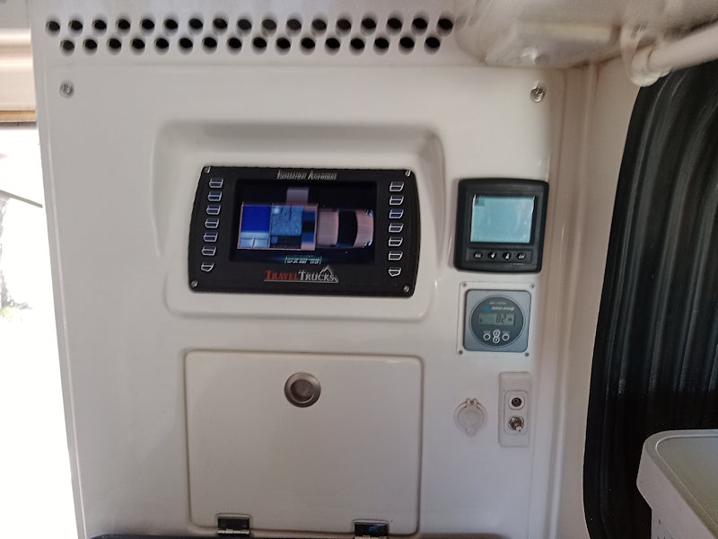
With extended use, the inverter can get hot unless well ventilated. It incorporates a fan and has clearance on all sides (but not the top, which is close to the base of the seat cushion). I have included a big vent in the hatch door, and drilled a large number of holes in a pattern of two rows in the wall above the Touch Screen. The natural ventilation should help.
The Remote Control Panel joins the Inverter using a CAT-5 cable.
A plastic vent in the hatch to the compartment housing the inverter.

Two rows of holes drilled in the wall above the Touch Screen provide ventilation.

Victron Phoenix Power Control Panel is on the wall near the cooktop.
230V Wiring
Because of our decision to use an induction cooktop for meal preparation, I had to install 230V wiring and an inverter capable of powering it. A design maximum continous power level of 2500W (200A @ 12.7V) would allow one cooking element at full power, or two at reduced levels, using the de'Longhi DE302 1B Induction Cooktop. In fact, I designed for 300A maximum load — this is still less than 85% of the 1C rating of the battery though it is more than the inverter can supply continuously.
Having 230V available is necessary for other purposes such as running m'lady's hair dryer and various chargers, so I included a number of power points, including one in the storage area.

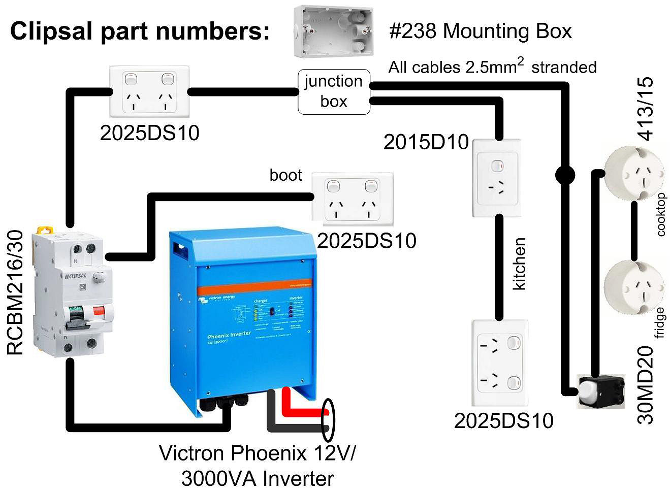
The design schematic is as follows:
The component choices and installation were supervised by a qualified electrician and the completed job was issued with a Certificate of Compliance. Most of the wiring was located in the channels around the skirt of the pop-top and were required to be enclosed in conduit. The power points and junction were built into mounting boxes inside the channels, sealed with silicone. The power point in the storage area (boot) was joined to the Safety Switch by cable enclosed in exterior grade rigid conduit screwed to the under floor of the camper using brass saddles.
Cross-vehicle channel at front of camper being fitted out. The cables will be in rigid conduit. This is the junction box.
Behind the RH side channel: over the sink. Mounting Boxes are being bolted and sealed to the channel.
Behind the RH side channel: over the cooktop.
The junction box in the cross-vehicle channel. One cable goes down the wall to come up in the space below the cooktop.
The junction box with a blank plate over it.
The installed power point over the cooktop.
The installed power point over the sink.
Wiring in the power point and isolation switch for the cooktop.
The tester shows all is good.
The circuit breaker/safety switch under the LH seat. One cable goes around behind the inverter (on the right) for the point in the storage area. The other goes up next to the Touch Screen and to the cross-vehicle channel.
A branch line to the storage area goes through the floor near the water inlet pipe.
Under the floor: the cable to the storage area is in heavy-duty conduit.
The conduit goes up through the floor next to the toilet cassette door.
The mounting box for the storage area power point is above the toilet cassette door.
AC wiring to the Victron Inverter. The E-N bond is the visible link. The cabinet is grounded to an Iveco-approved ground bolt on the chassis. The blue Cat 5 ethernet cable goes to the Victron Inverter Control Panel above the RH camper seat.
LINKS
