Solar Setup
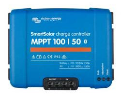
Victron 100/50 MPPT Solar Controller
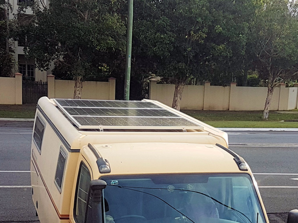
Victron Solar Panels on TT30
Scrubmaster TT30 has three new solar panels. They are Victron 215 Wp monocrystalline panels, and are the same size as the original Voltech 12 V panels with much better performance. They are matched with a Victron SmartSolar charge controller located behind the Touch Screen in the camper and this is managed by the VictronConnect App on a Smart Phone. Alternatively, a Victron Solar Display is also present to manage the charge controller.
Performance of the Solar System
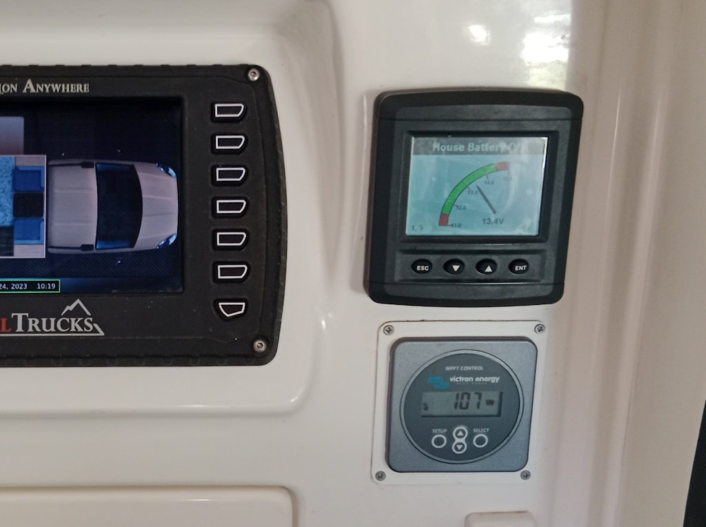
Victron Solar Display below the Systems Monitor.
The solar system is working well. On a clear day I am usually seeing about 30A into the battery — so much better than the peak of 25A I rarely saw from the OEM setup.
The solar charging is set by the Victron Connect app to charge a LiPo battery. The maximum absorption voltage is 14.2V, and this should be safe for the lithium camper battery.
The first image is a screenshot of the history of outputs over five days of favourable conditions. Peak efficiencies were between 70% and 85%, very credible results!
The second image is a screenshot of the real-time output from the Victron regulator in ambient temperature ~35°C. The overall efficiency of the solar system was 71% at that time.
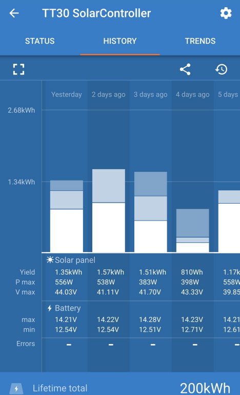
History plots over 5 days from controller.
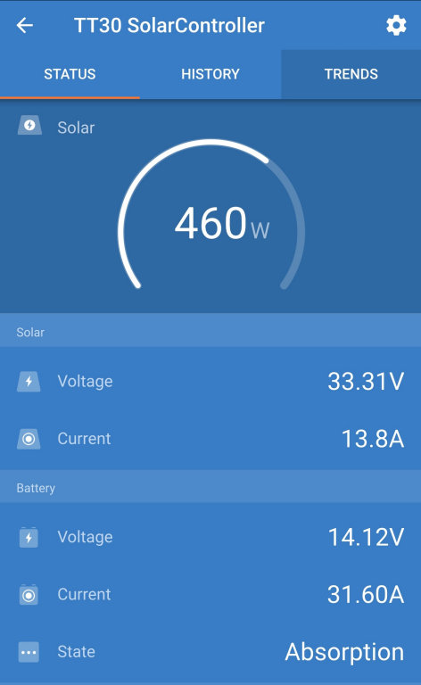
Real-time results from the solar controller.
Trickle Charging Starter Battery
I think a trickle charge to the starter battery is desirable. Here, during the day so long as the solar panels are on, the starter battery receives a charge from the camper battery limited to about 1A, whether or not the solar controller is on. At night,charging of the starter battery does not occur. (For longer term storage, the charge to the starter battery can be stopped by cutting off the solar panels using the solar panel circuit breaker.)
Isolating the Camper Battery
The Camper Battery can be isolated by using the switch next to the passenger seat. But this does not stop power from the solar system feeding into the various loads, possibly causing various strange effects. The solar controller circuit breaker behind the hatch below the Touch Display can be used to cut off this power source.
Replacing the Solar Panels
It was a difficult job removing the original panels due to the way they were installed. The panels were glued to the roof sides along their short edges and to the centre of the roof at the centre of the long edges. Panels 1 and 2 were held together with two heavily rusted bolts. I found the best way to cut through the adhesive on each side was to use a box knife extended to 40 mm and lots of soapy water. A steady force with the knife against the edge of the roof and job done. The central mound of adhesive between panel 1 and panel 2 required use of a 1 m long chisel (3mm x 30mm steel) and a hammer. Then panels 1 and 2 could be lifted up and the joining bolts cut through using a hacksaw blade. Removal of panel 3 required removing the piece of aluminium angle that had been used to hold the panel to the centre of the roof. This was quite difficult, since the adhesive thickness was very thin.
I replaced the original 12V solar panels with 24V versions and mounted them on domestic solar track to give better airflow under the panels and to make servicing easy.
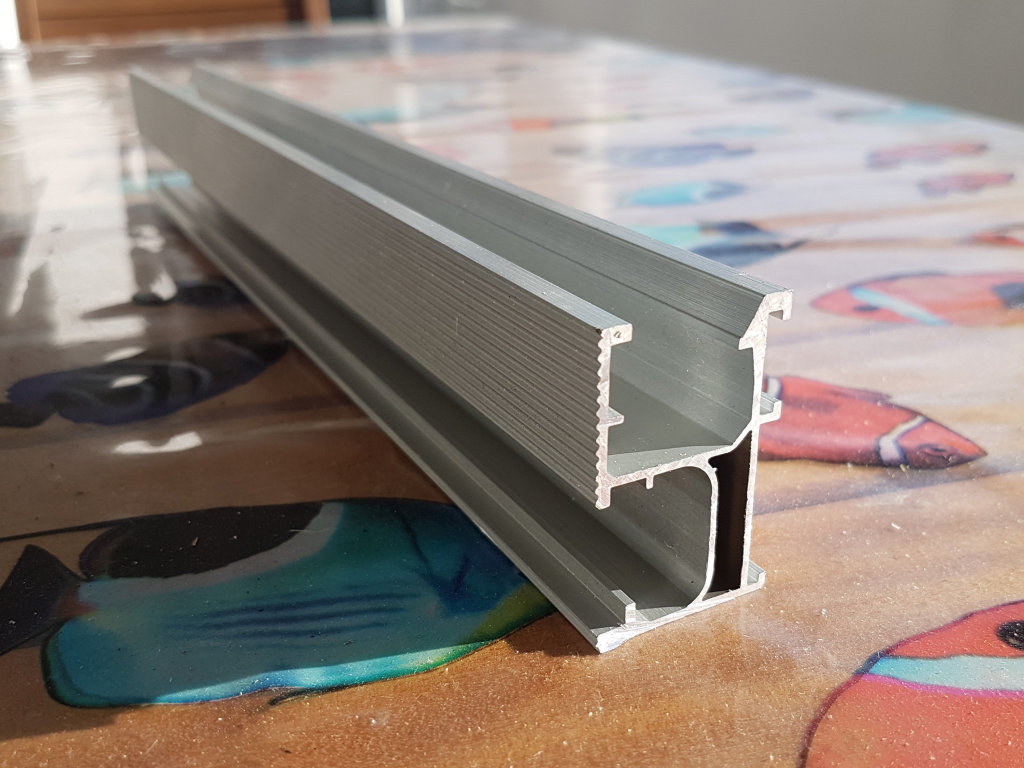
The solar rails are 32mm wide x 50mm high x 2.7m long. The roof bows a bit when down and a little more when raised — 7mm and 12mm. Gluing the rails to the roof with a thick adhesive bead should allow for this change.
- I bent the rails by standing on them until they too were bowed by 7mm at the centre.
- The roof was cleaned thoroughly using soapy and clear water.
- A length of 12mm x 4.5mm foam tape was laid down along the centre of the bottom of each rail.
- I laid a bead of adhesive on each side of the tape, trying for about 8mm thick.
- With a friend's help the rails were then turned over and set in position, pressed down and left for a day.
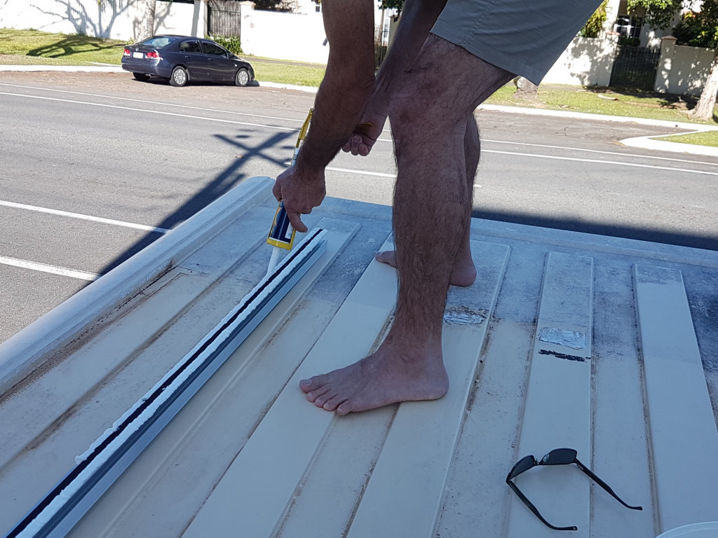
Laying down an adhesive bead.
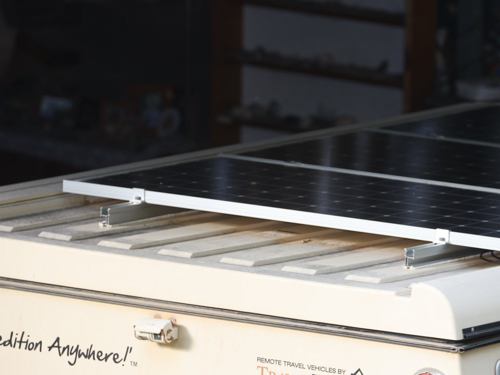
Tracks glued, panels clamped down.

Three solar panels installed - note air gap.
I could not make up my mind whether to use Bostik Extremely High Initial Tack MSP Adhesive or their Extreme Flex MSP Adhesive (said to be UV resistant (but both are) and flex to 400% of thickness). So I laid down beads of each kind on each rail, each bead taking a full cartridge. These Bostik products are amazing Silyl Modified Polymer (SMP) adhesives and are so much easier to work with than the Sikaflex products and perform better too.
The new panels are Victron 215Wp nominal 24V (42V actually) monocrystalline panels, and are the same size as the original Voltech 200Wp nominal 12V panels. The higher panel voltage means earlier startup and later shutdown in the evening and more headroom for the MPPT part of the controller to operate. The extra 15Wp per panel is nice to have. The panels are clamped to the rails using standard domestic 35mm solar panel rail clamps tightened with an Allen key. There is now a gap of over 55mm below the panels for good airflow and they are supported at about 1/4 length instead of at their ends so flexing is reduced.
Jaycar sells a patch cable 50A Anderson to MC4 solar (PS5122) that plugs into the Anderson connector on the roof. A couple of pairs of MC4 Y-cables (PS5112 but much cheaper on eBay) completed the connections of all panels in parallel. It soon became apparent that the 30A circuit breaker for the charge current had to be increased; I replaced it with a 50A breaker.
Notes on Setup and Performance
The setup of the Solar Controller can be found here. The second performance image above is a screenshot of the real-time output from the Victron 100/50 regulator. It shows that the panels were producing 460W in the favourable but hot conditions prevailing. And even though almost fully charged, the battery was receiving 32A at 14.1V = 446W, giving a regulator efficiency of 97%! Since the panels total 645Wp, the overall efficiency of the solar system was 71% which is very credible for hot conditions.
Trickle Charging the Start Battery
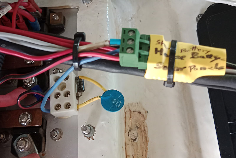
Trickle Charger: blue bit is thermistor - it gets hot.
The original solar regulator, a Votronic unit, was able to give a trickle charge to the start battery to keep it in good order when parked up. The replacement Victron is not able to do this, but I can achieve a similar capability by trickle charging from the camper battery but only when the solar panels on TT30 are active. I use a MOSFET to switch the trickle charge off when the panels are in dark (at night), otherwise the camper battery might charge the starter battery then.
Take camper battery power from the back of the circuit breaker for the solar regulator (joins the camper battery). Then connect this via a 3A diode, a PTC C945 thermistor and an N-channel Power MOSFET to the wire labelled F8 which goes to the starter battery.
The MOSFET is triggered ON (this requires a voltage above 4V at the Gate pin relative to the Source pin) by sampling the solar panel voltage at the input to the solar regulator. The voltage is clamped to 5.1V and applied to the MOSFET Gate pin. Hence the Gate pin voltage is always well below its design maximum of 20V.
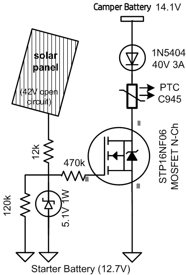
The result is that during the day the start battery receives a charge limited to about 1A due to the action of the PTC thermistor, so long as the start battery voltage is less than the (camper battery voltage - diode voltage drop). At night, the solar panel voltage drops to 0V and the MOSFET is turned off, so charging the start battery does not occur.
For longer term storage, the camper battery needs to be isolated so turn off the solar panels at its breaker behind the Touch Screen so it does not continue to send charge to the starter battery.
Test measurements:
- Camper Battery voltage 14.1V
- Start Battery voltage 12.9V
- Solar Panel voltage 39.8V
- Diode voltage drop 0.36V
- PTC themistor voltage drop 0.58V
- MOSFET voltage drop 0.1V
- Charge current 0.78A.
LINKS
