The roof is double-skin fibreglass, heavy, can be walked on (when down), holds the solar panels (50 kg) and the LH awning (18 kg). The roof is a pop-top, rising approx 500mm using a set of Linak linear motors or actuators, one in each corner of the camper, driven by a Linak supply/controller behind the LH camper seat. The linear motors can easily manage the load. When travelling, the actuators keep the roof in position and are kinetically mounted to absorb road shocks.
A pair of push-button switches at the side-entry door activates the raising and lowering of the roof. They are wired to the CAN-Bus electrics, as is the Touch Display and all that that controls.
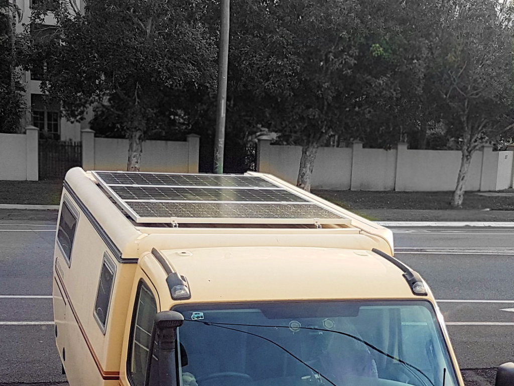 Pop-top roof and solar panels.
Alternatively, a rocker switch inside the camper below the LH camper seat is directly wired to the Linak supply/controller. The roof can only be lowered or raised if the ignition is off and the handbrake is on. Sometimes the CAN-Bus side-entry switches do not work anyway and the other, directly wired, rocker switch must be used.
The Awning is discussed on the page Camper and the solar panels mounting is on the page Solar.
If at times the roof appears not to be fully down on all corners then see the note at the end of this page for a solution.
Problems and Solutions
There have been several failures of the roof, causing lots of stress. Solutions have been found and implemented.
No Response to Signals
The Linak controller is Type TR-EM-273. It is a parallel synchro controller for the DC motors at each of the four corners of the roof. At about 68,000km odo the controller suddenly refused to respond to the switches, and continued this way even after various attempts at resetting, power down periods, etc. TravelTrucks made many attempts to help remotely and after a week with no success, made up and couriered a wiring loom to us that allowed temporary direct operation of the roof actuators. This wiring loom is tied to the controller cables in case it is ever needed again.
4,000km later we were at TravelTrucks for a different repair. They tested the controller from TT30 and found it to be fully functional! There has been no recurrence of this issue.
I now know that all the drama and inconvience was unnecessary.
The Linak Controller
The Linak controller is mounted behind the LH camper seat below the touch screen in a purpose plastic box with RESET, UP and DOWN buttons on the side that can be reached from inside the storage compartment below the seat. If the roof fails to lower or there is some other failure of the roof or its mounts, buttons on the side of the Linak supply/controller can be used to override the normal control switches.
Pressing and holding the RESET button (for at least 5 seconds) until after the roof is fully down will likely restore functionality. This is called 'starting a "home run"' and recalibrates the fully down position. (The procedure may need to be repeated until all corners of the roof are fully down.) The problem with the controller can be checked by removing the cover and observing the FAULT LED: steady red says the actuators are presently in operation; flashing red 1 blink (current limit), 2 blinks (pulse lost), 7 blinks (position data corrupted), 8 blinks (home run/learn fault).
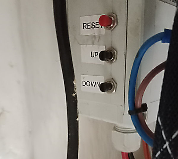
Buttons to directly talk to the LINAK Controller. RESET (pin 23), UP (pin 20), DOWN (pin 21) on the Controller.
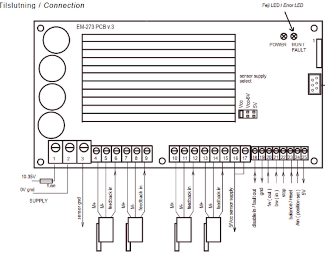
Diagram of the LINAK controller showing location of POWER LED and RUN/FAULT LED which flashes an error code.
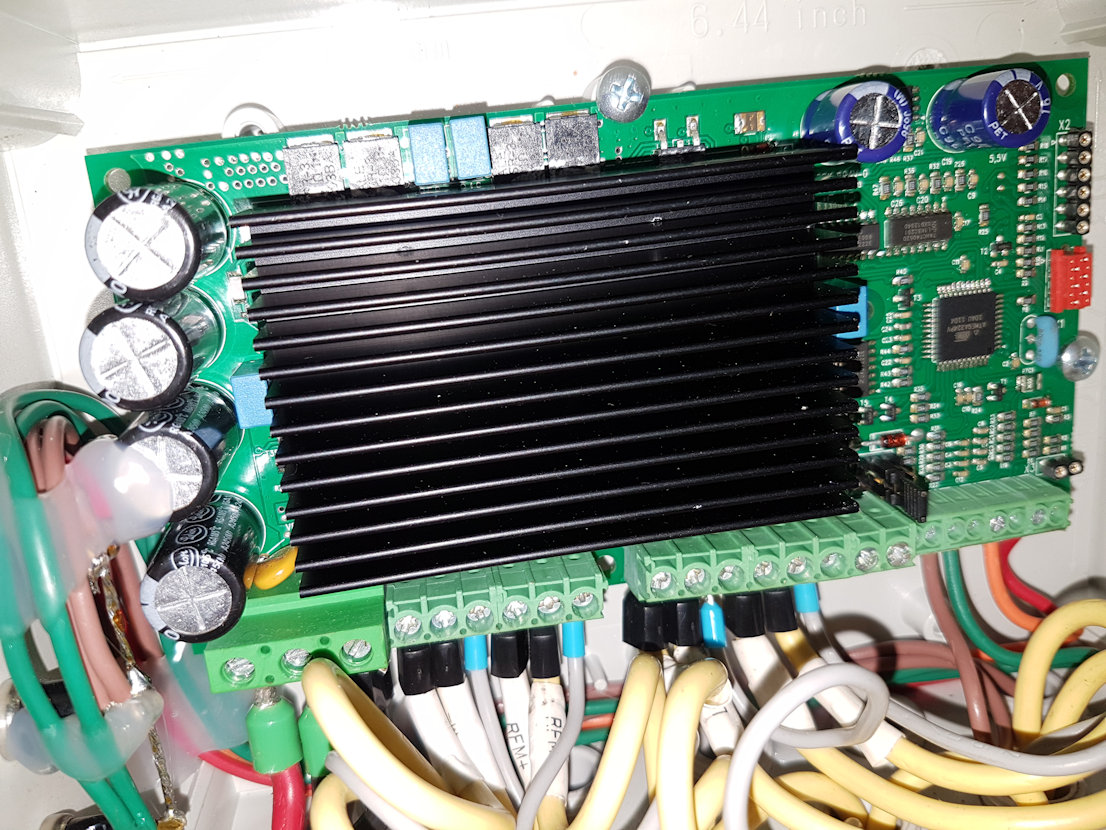
The LINAK controller wired in TT30.
So the drama at 68,000km could have been fixed by simply holding down the RESET button on the controller box until the roof fully lowered, repeating this until all four corners were down. The "home run" would have reset the system. Instead, I was told to use the DOWN button to lower the roof so we could at least travel with roof down, but this does not restore functionality!
Mount Bracket Failure
Early Scrubmaster campers such as TT30 had the linear motor support brackets made of aluminium angle 5mm x 100 mm x 80 mm with no strengthening gussets. It should have been no surprise that flexing, even ever so slight, occurred as the roof moved up and down on rough "roads" and led to fatigue failure of the bracket. TravelTrucks has made later campers with the bracket inverted and made of steel to resist flexing!
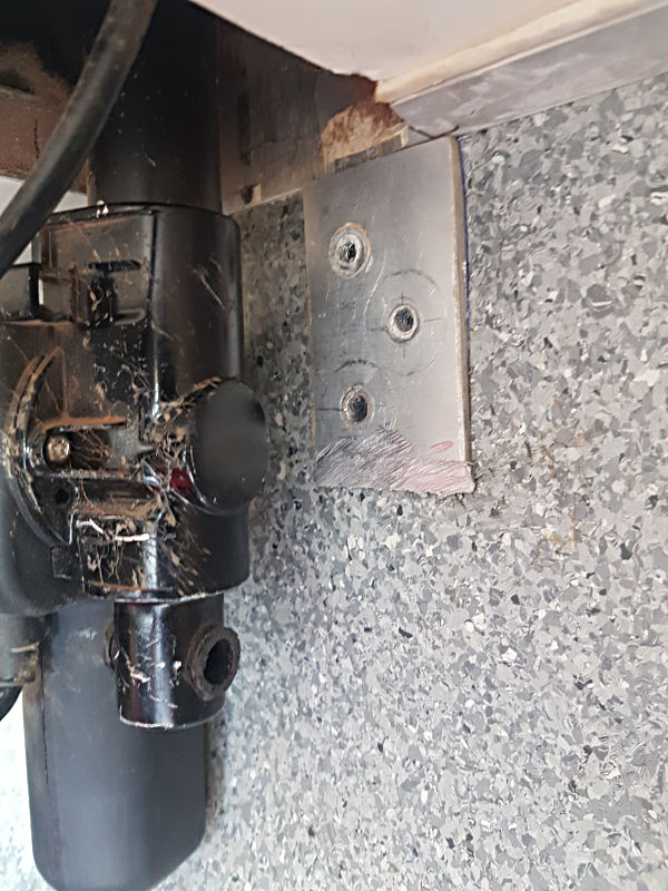
The vertical web after failure and fracture dags ground off. In the field I could not remove the web from the wall.
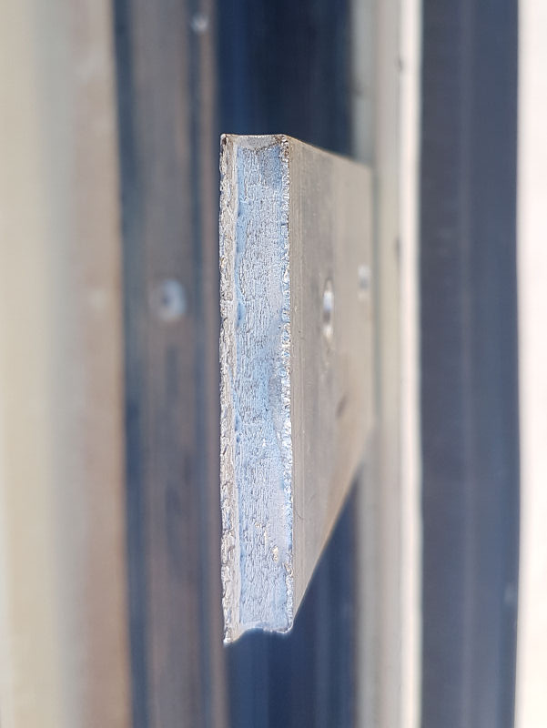
Close-up of the fatigue fracture. The right-hand edge was underneath. That edge was the last to break by rapid flex.
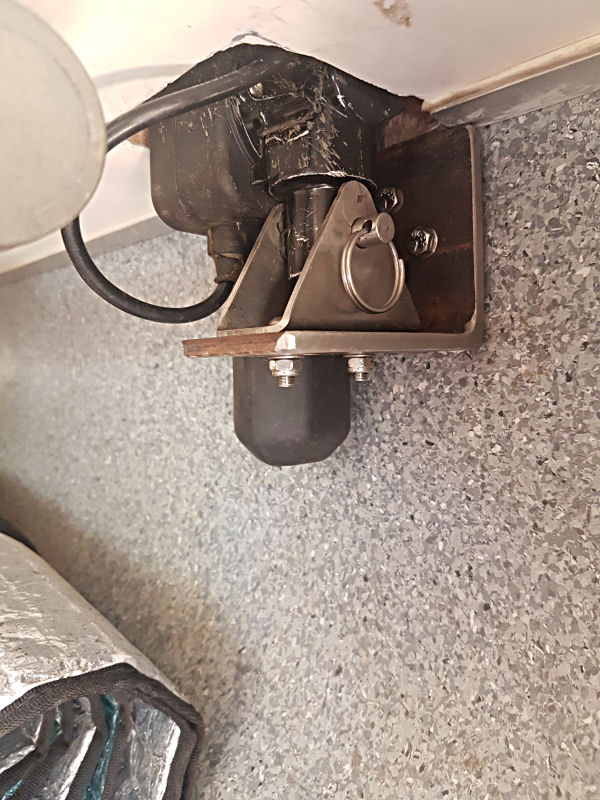
New steel bracket bolted to the camper rear wall holding the Linak linear motor. Note the rigid mounting method for the motor.
At about 72,000km I discovered the broken LH Rear bracket one evening as I raised the roof 110 km from the nearest town (Winton, S Qld). We were very lucky that the motor cable had not been stretched to breaking too. So after some difficult adjustments we got the roof up and assessed that a new L bracket in steel would be necessary. Next day, we called upon Diamantina Engineering in Winton who were able to cut and drill two brackets in 6 mm steel. Since we could not remove the original vertical web, the new bracket had to be bolted over it using M6 x 30mm hex-head bolts and the motor support hole positions moved by 5mm.
During our next visit to TravelTrucks to fix the next roof failure (see below) all mount brackets were replaced with steel ones.
Linear Motor Failures
At about 76,000km I observed that the Front RH roof actuator was not functioning. This was the first of a long series of failures of the Linak actuators on TT30. We have had seven (7!) actuator failures, all due to the same cause, and each one hugely inconvenient and time-consuming.
Drive Nut Failure
The roof lifting actuators are linear motors: a worm-drive motor at the bottom of the unit rotates a long Acme-thread rod called a spindle. The rotating spindle causes an Acme-threaded nut captured at the bottom of a tube to rise or lower; the tube is attached to the roof, taking it with it. The actuators are Linak Compact LA28 type 2814RG-00750220. They are specified to push or pull up to 2000N.
TravelTrucks had no idea how to fix this short of somehow using latches on the corners of the roof to lock it down while travelling – an impractical solution. Linak, originally involved in the design of the Scrubmasters, washed their hands of the problem and refuses to warrant the application of the actuators on the vehicles.
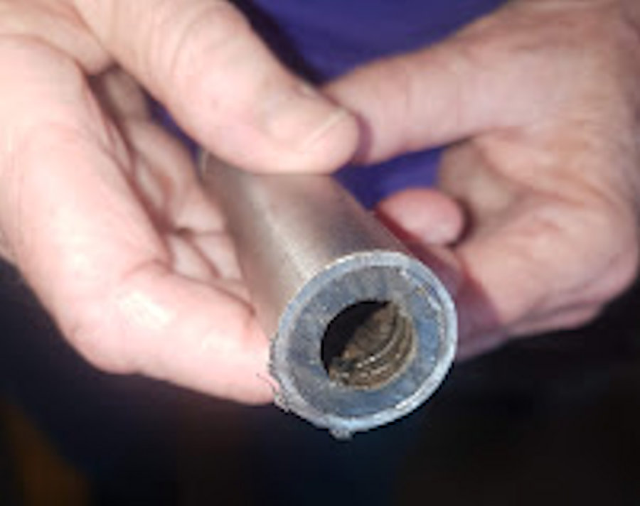
Cut through the actuator nut shows Acme thread worn away.
I was early-on told that the actuators off-load the weight of the roof when the latter is in the lowered position, but that is not correct. While the motors do off-load the worm drive when fully retracted, the drive nut, made of a metal-filled plastic, is always under load whether the roof is down or up. On rough roads the roof rises and falls slightly in response, placing much higher shock loads on the actuator nut than what at first sight appears to be an easily managed load.
At one stage TravelTrucks staff cut open one of the failed actuators. It was obvious that the thread in the drive nut had been completely worn away. It also appears that the composition of the nut has changed over time: more recent failures have occurred after only relatively short times.
Four failures on, I proposed a solution to TravelTrucks. I reasoned that it is not possible to stop the roof vibrating up and down when travelling; the vibration had to be dampened so the shock forces on the actuator nuts are reduced to safe levels. I proposed mounting the triangular support of the actuator with rubber between it and the steel mount bracket. And adding another rubber sheet and steel plate below the steel bracket. See my sketch here. When stationary with the roof down, the roof would not load the bracket. When travelling, both downward and upward forces on the actuator are damped by the rubber sheets before being transferred to the steel bracket through the drive nut.
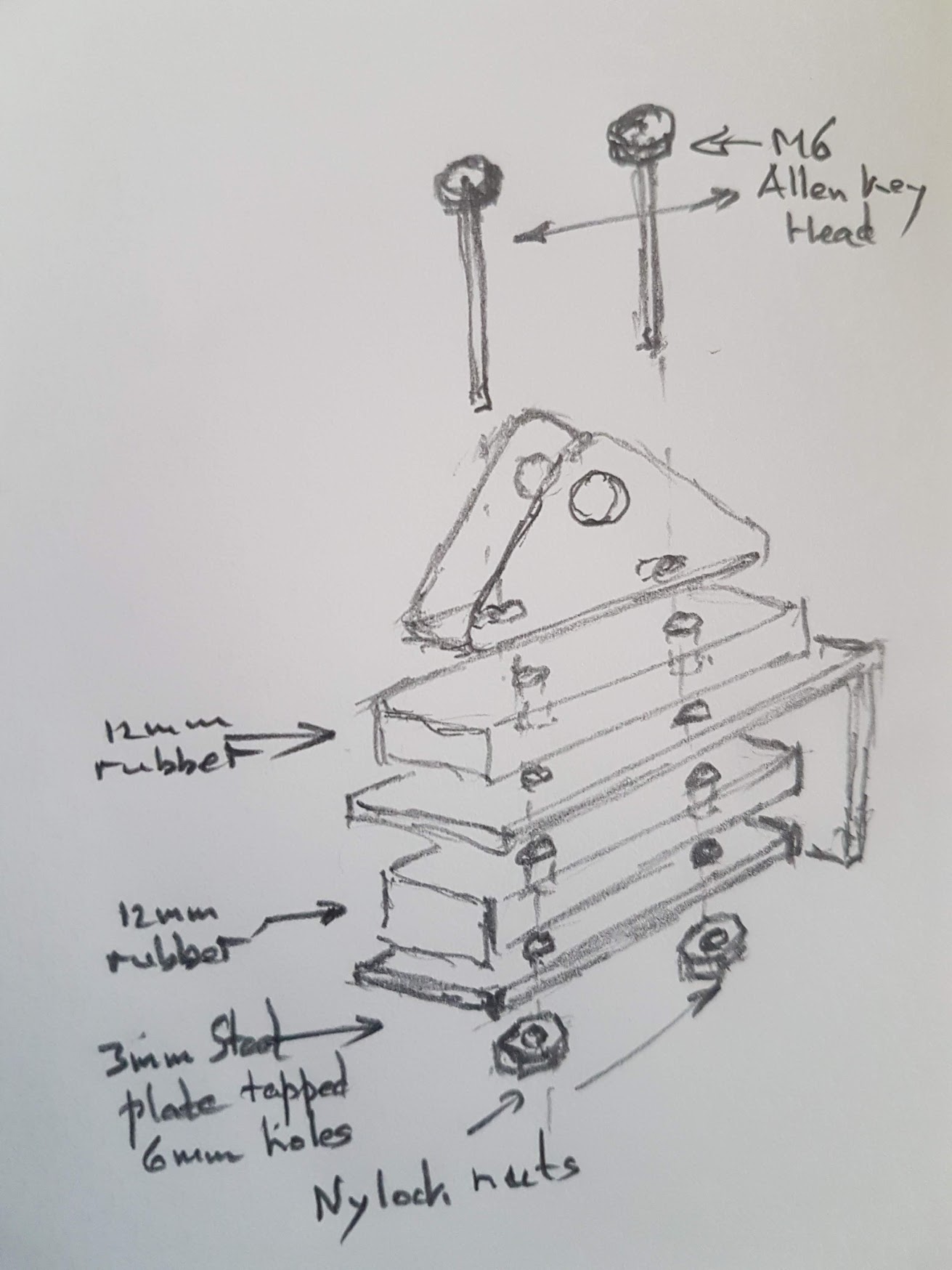
My proposed solution to dampen loading
on the actuators using rubber blocks.
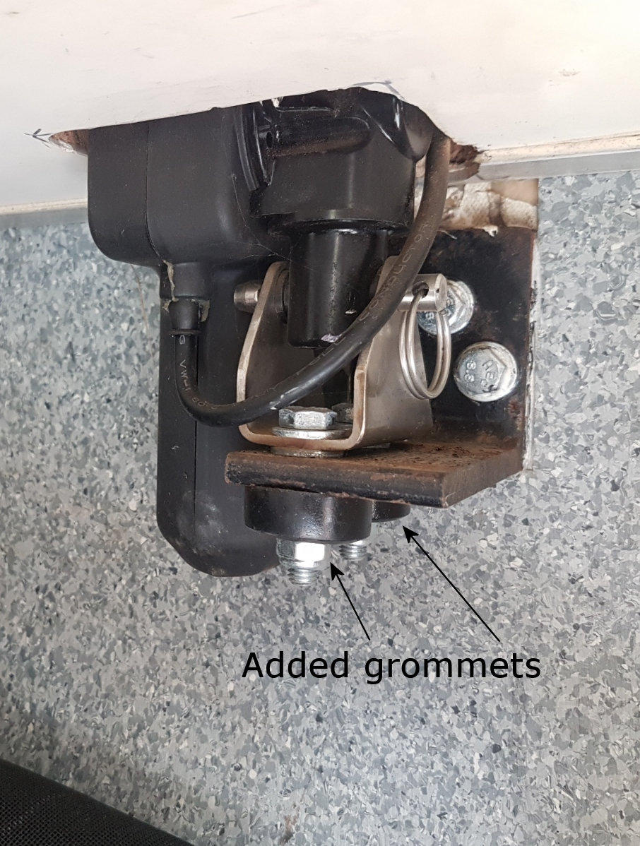
TT partial solution: grommets for
upward roof movements.
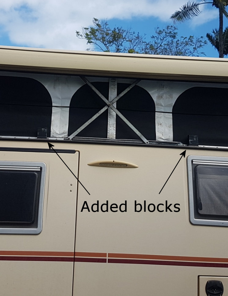
TT partial solution: blocks for
downward roof movements.
TravelTrucks accepted some of this: they thought that dampening downward motion this way might throw out the count of pulses from the rotating Linak spindle. For upward motion they used my approach but chose to use large rubber grommets and steel washers in place of sheets of rubber and steel (indeed a more practical approach). They also installed two large plastic blocks on each side of the top of the camper body so the roof when lowered would rest on these. This would also stop the roof skewing.
More failures: it appeared that with only one way shock dampened, the shock loads were as bad as ever, perhaps even exacerbated by rebound forces since failures were becoming more frequent.
TravelTrucks agreed to add upper grommets to dampen downward vibration but used only half-height grommets. There was still substantial load on the upper grommets with the roof fully down — the upper grommets were compressed and distorted, missing mudguard washers. Hence dampening was not effective.
Another failure occured. The repair by TravelTrucks for this used full height grommets for the first time and the brackets and roof blocks were adjusted so that both upper and lower grommets were not heavily loaded when the roof is down.
August 2022 and 130,000km odo a trip to The Tip and back to Cairns really stress-tested the roof actuators; the bypass roads and south to Moreton Telegraph Station on the Wenlock River were heavily corrugated. Although we returned to Cairns without incident, it soon became apparent that the front actuators were in fact in trouble.
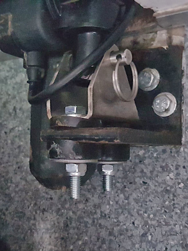
Upper half-height grommets, loaded up.
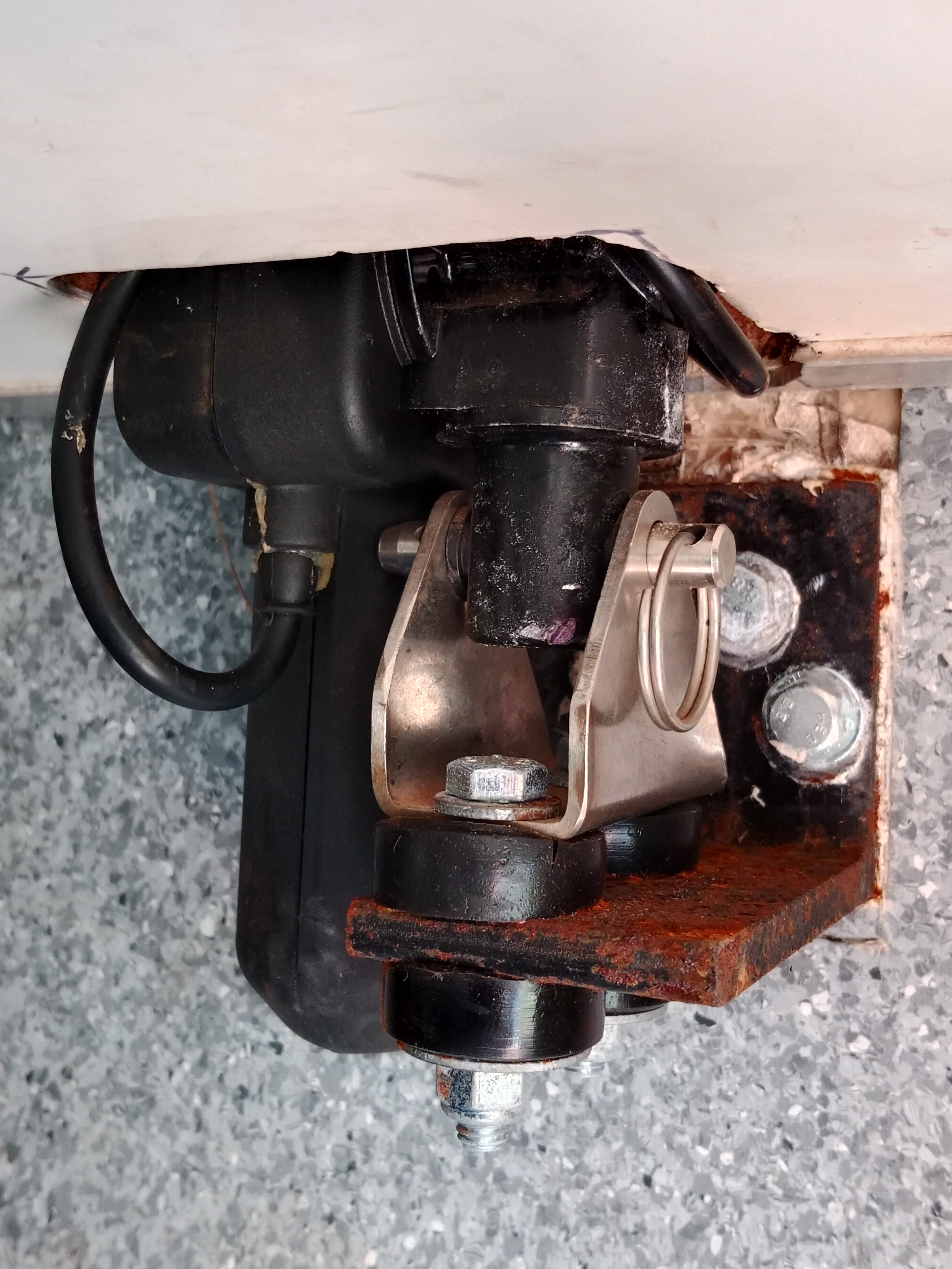
Full implementation of proposed solution.
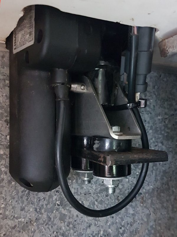
Same for RH rear actuator mount.
Failures due to Poor Workmanship
Soon after returning to Cairns, with very little more travel, the LH front actuator drive nut failed. And soon after that, the RH front actuator drive nut failed! I examined the mountings and found a common problem — sloppy/bad workmanship. For the LH side the grommets were all correctly in place but the pin holding the actuator motor to the triangular base was almost out. No doubt the actuator was able to vibrate badly once this had occurred, leading to the failure.
Not willing to return to Brisbane for the repairs I replaced the LH front actuator and upon trying to insert the holding pin found what the issue was — the pin could not be pushed in all the way because it hit against the rear wall of the LH camper seat. I drilled an oversize hole in the rear wall and the pin now fits correctly!
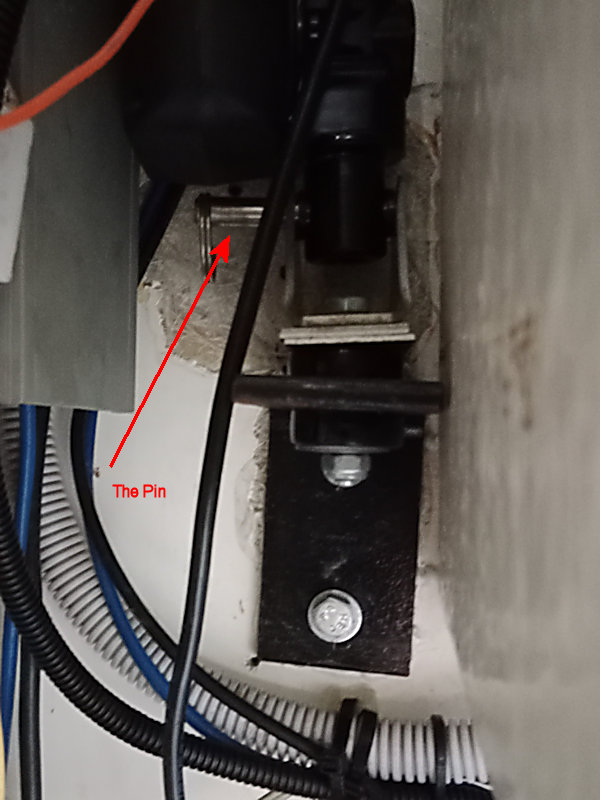
Found: LH mount pin almost out.
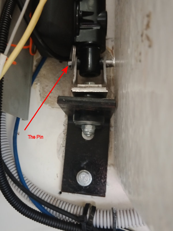
LH mount pin inserted, into hole in wall.
One of 4 Roof Mount Blocks.
I examined the RH front actuator mount and saw that while the pin holding the actuator motor to the triangular base was fully home, the whole triangular base was loose on its mounting bolts holding the grommets and washers. Indeed the front mounting bolt was exceptionally loose. The reason is that it is simply not possible to do up that nut tightly — there is no room to put a spanner on the bolt head to stop it turning. No doubt this sloppy assembly issue led to bad vibration of the actuator and another failure.
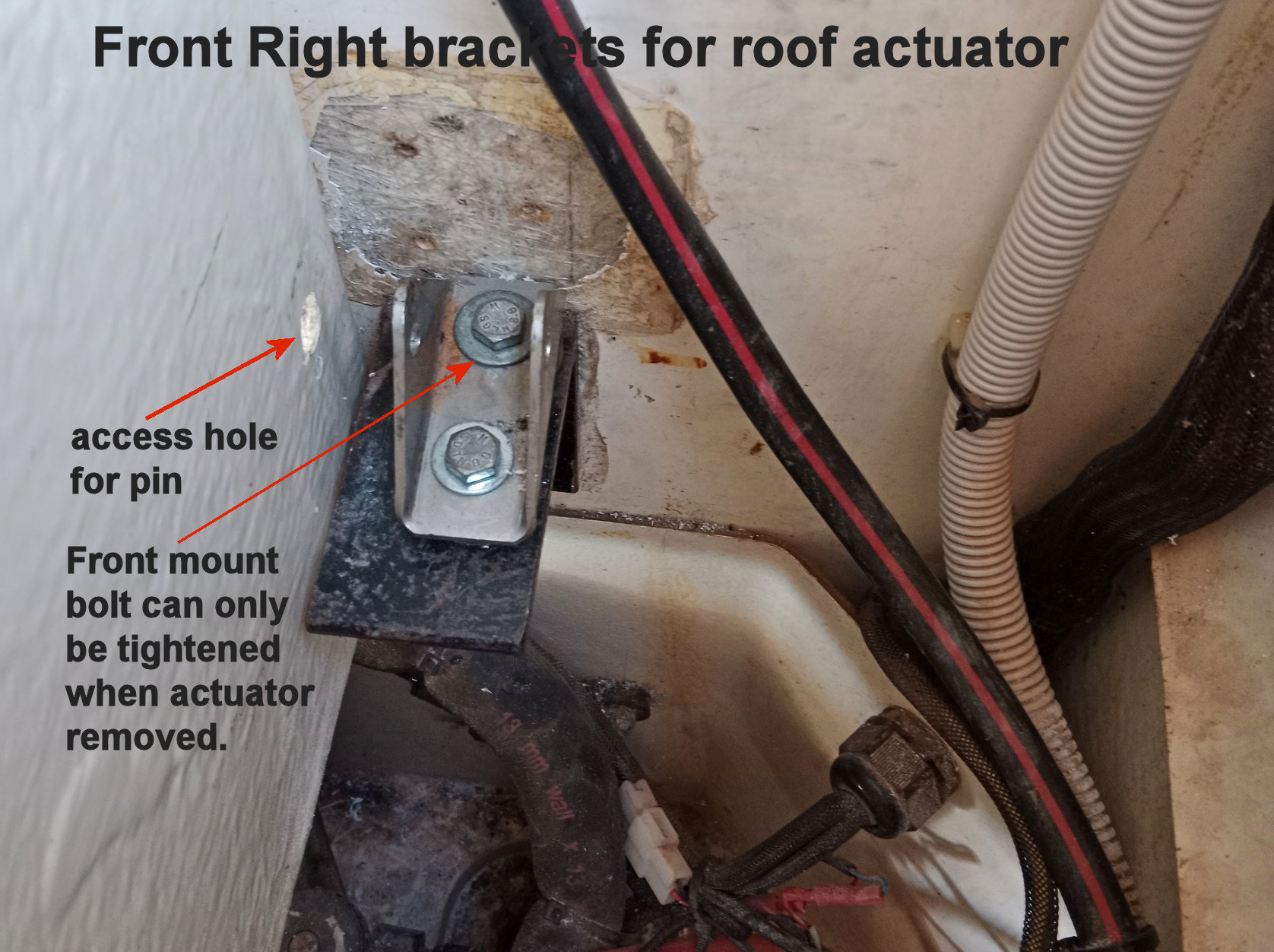
RH front mount bracket and wall bracket for roof actuator.
Due to poor design, replacing the RH front actuator has been a major task up to now. It required dismantling the storage box behind the seat, disconnecting the heater air exchanger electrics and its plumbing, and moving it out with the seat frame along with the actuator cover before removal of the actuator itself was possible.
Instead, I cut the fibreglass actuator cover away from the seat frame using a multi-tool, and made up threaded plates to bolt behind the cuts to strengthen the reassembled components. The cuts would then be filled in with silicone sealant. By removing only the actuator cover it is easy to replace the actuator.
The correct way to install the RH front actuator is to bolt the triangular base to the steel wall bracket with all the grommets and washers in place. With the weight of the roof supported, hold the actuator over the triangular base and insert the holding pin through a newly drilled hole in the rear wall of the RH camper seat. Wind out the actuator arm sufficiently to line up with the roof mount bracket and insert the holding pin there.
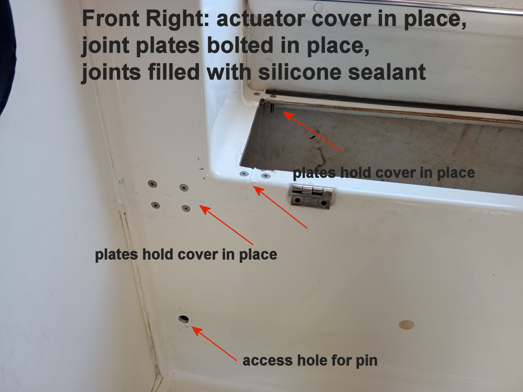
RH camper seat frame and actuator cover bolted together.
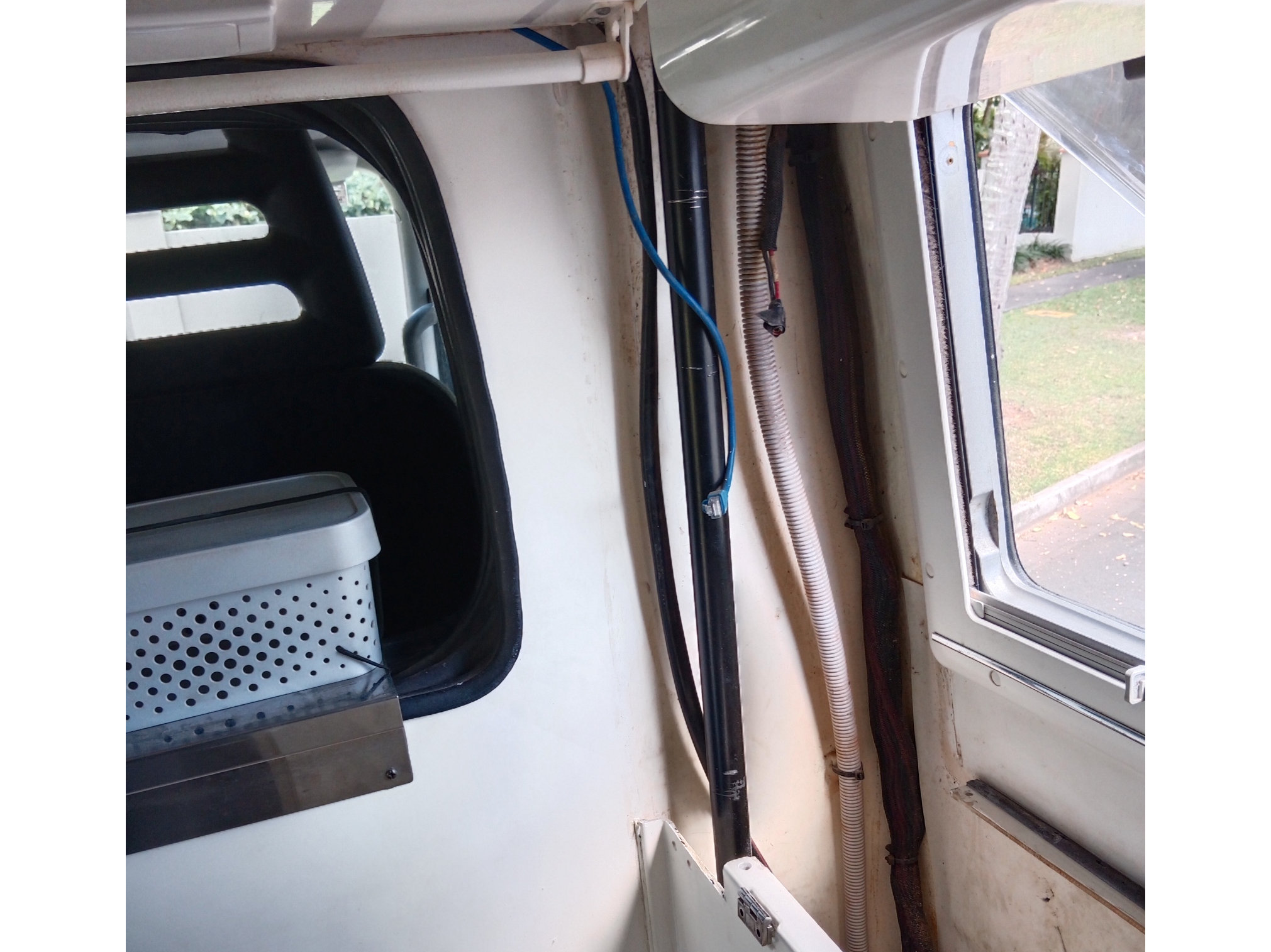
RH front actuator cover removed to give good access to actuator.
RH front actuator cover and seat squab back in place after installation complete.
Actuator Replacements
The procedure for actuator replacement is the same for all except the RH front: support the roof in position using wooden posts, remove the holding pin for the actuator arm at the roof end, wind down the arm by hand, remove the holding pin from the motor end and slip the whole actuator out after unplugging the electrical connection.
Replacing the RH front actuator (behind the driver's seat) requires first removal of the storage box and lid behind the RH camper seat, cut through the silicone sealant in the cut between the fibreglass seat base and the fibreglass actuator cover, remove the three strengthening plates behind the joints, and remove the fibreglass actuator cover. Then proceed as for the other actuators.
Roof Down Fully
I have noticed that one or other corner of the roof tends over time not to go down fully, compromising the weather seal between roof and module. This may be a consequence of TravelTrucks not relocating the mount brackets for the actuators following installation of the upper kinetic mount grommets. A solution is to (i) raise the roof 200mm or so and then (ii) reach in through the LH under-seat storage hatch and (iii) press and hold the RESET button (top red button) on the side of the Linak Controller box until the roof is completely down + 5 seconds. This resets the down position.
LINKS
