The Installation of Airtronic D2 Air Heater
What is said to be a 3 hour job in a truck ( Espar installation video), took me about 4 man-days plus several days of thinking and looking in the A'van Applause 500 for the installation.
Where to locate the Heater
The heater unit is compact:  Connections
are:
- Hot air ducts 60 mm diameter, both inlet and outlet
- Combustion air inlet is 25 mm diameter
- Combustion air outlet is 24 mm diameter
- Fuel line is 4 mm diameter
- Electrical connection block with 5 A and 20 A fuses, wiring for power, heater controller and fuel metering pump.
The heater needs to be located out of the way, not in a valuable cupboard space, but protected from the weather and able to be serviced when necessary. The heater controller needs to be close at hand while we are in bed!
I settled on locating the heater below the table, against the wall and under the raised floor that the table is mounted on. The heater controller would go on the wall of the shower/toilet near the Truma hot water controls. These decisions threw up issues that became apparent only after the kit compiled by Dometic Australia was purchased.
Hot Air Ducting Impedance
The Airtronic D2 with 60 mm diameter ducting has an air flow impedance rating of 6 units. If the proposed ducting arrangement has a flow impedance greater than this then unsatisfactory hot air delivery and possible overheating may occur. The installation instructions supplied with the kit note the impedance rating but are otherwise silent. The Espar Web Site has information in the 2012/2011 Espar Product Catalogue, pp67–69. The section on duct impedances is available here (file 486 KB).
 The proposed ducting would have a hot air
inlet (1) close to the front of the van and opposite the fridge, the duct turning
(3) to enter the heater against the outside wall of the van and then from the outlet
to a "Y" connector (5) straight through to the shower/toilet (7), and on the branch
turning (8) to run along the wall behind the rear seats and to a rotatable outlet
(9) exhausting to the house space opposite the sliding door.
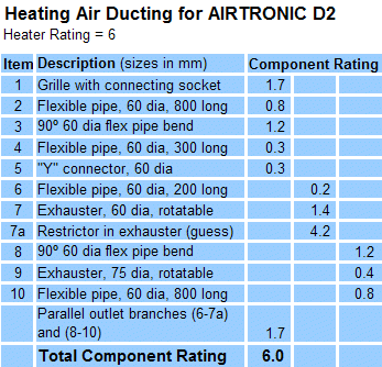 My calculation of the ducting rating is shown
in the Table. Since the air flow to the shower/toilet is much shorter and direct
than to the house space, we need to add some blockage to the shower/ toilet line to
balance the flows. The impedance of this blockage needs to be guesstimated - it is
expected to be rather severe, so a substantial value is used. Even so, the calculation
of overall impedance is not sensitive to this value, which can range between 3 and 6
for a 20% change in total rating. The important finding is that the proposed design
is right at the maximum for the D2 with 60 mm ducting. Care is required to keep
restrictions to a minimum.
The Controller
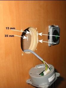 There is only 35 mm
clearance behind the shower/toilet wall, including a 20 mm cavity, but the rheostat
controller requires 60 mm clearance, including a cavity gap of 30 mm to feed the plug
to the controller, and has to be installed from behind. The mini-controller only
requires a few mm gap for a cable to be fed to it and is installed from the front. So
the rheostat controller had to be replaced. Dometic Australia were not
helpful, but mail order to
Autoteile-Discount24.de provided a mini-controller (they call it a controller for
a pre-heater) at a postage cost almost equal to the cost of the unit, but still
acceptable. The high quality cable (teflon core, high- temperature insulation) for
the original rheostat controller would be needed for the connector to the Airtronic unit.
The Fuel Supply
The installation instructions require that the fuel metering pump be mounted at an angle of at least 15° to the horizontal and the line from the fuel metering pump to the heater should be routed in a continuous rise. This is to ensure air bubbles and vapour in the line pass through the pump and line without causing a blockage.
The Ducato floor is so low, however, that it is not possible to meet both these requirements.
Installation Steps
Hacking into an existing setup where clearances and hidden wiring can only be guessed at, can be traumatic. It was in this case. Perhaps the most excitement was with the installation of the fuel pickup pipe. Read on.
The main unit
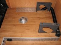
The heater main unit goes into the raised floor behind the driver's seat, against the van outside wall. I cut away the raised wooden floor, and the main wooden floor below, to the metal floor of the van. The depth is enough to comfortably house the main unit. At this location, the van floor is part of a box section running the length of the van below its outer and inner walls. (The main chassis is further inboard.) The heater unit is positioned as far rearward as possible, limited by baffles in this box section related to a wall seam in the van. I cut into this box section to allow the combustion air intake and exhaust outlet and fuel line to pass down into the channel and then out through the inner wall of the channel to the underside of the van. The width of the space for the heater main unit is greatly limited by the presence of an RSJ apparently placed to strengthen the body for the rear seats. Hopefully the pictures make this clear.
The fitting kit from Dometic Australia includes a large mounting plate with a ring designed to be installed in the wooden floor of a caravan. I knocked the ring off and removed some of the plate so it would fit in the hole I had cut in the wooden floors. I drew on experience with attaching the boat brackets and planned to use five 3/16" spring toggles to bolt the mounting to the metal floor of the van.
Hot air ducting
The hot air inlet ducting (the "air return" would go through the checkerplate side of the raised floor and at least one ply joist to turn through a right angle to meet the main unit. However, upon drilling with a 72 mm hole saw through the side, I discovered an RSJ extending forward, a little beyond where the ducting would go! This was the second RSJ to strengthen the mounting for the rear seats, but it is much longer than the one near the outside wall. I concluded that this RSJ at this location was not structurally important, and since it was close enough for the hole saw to reach, I sawed through it, leaving the lower web and a little of the upright! Upon finishing to full depth this hole with a hacksaw blade, I discovered another ply joist. This and the one near the outside wall were cut away enough for the ducting to pass, using a 30 mm extension on a 18 mm spade bit and piercing saw with an extended handle. This took a lonnngg time to complete.
The installation of the hot air outlet ducting was uneventful. For the straight branch I used the 72 mm hole saw to cut through the ABS plastic wall of the shower/toilet and to keep going through two layers of ply wall. The branch line for the main house space is fed behind the legs of the rear seats and is wedged in position by the outlet fitting.
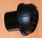
I have revised the main hot air outlet duct coming off the Y branch. The straight section is now a 75 mm smooth metal tube (downpipe), with the air outlet fitting directly into it. At first the supplied variable vane air outlet was used, but the vanes are too easily knocked closed so a second standard air vent was bought from 'dieselheaters4u' off eBay UK and fitted. A heat shield and cover surrounds the outlet fitting. The result is lower flow resistance and a neater appearance.
Installing Fuel Pick-Up Pipe
Diesel fuel is supplied from the Ducato fuel tank. A SBMCC Forum post notes that
The ducato is very easy to install a tank feed into. If you remove the inspection cover by the passenger seat, you'll see another seal - unscrew this and you'll see the top of the tank with its sender unit connections. If you hold these to one side there is space to send a drill and stepped cone cutter down there to drill for the hole, then you can feed the pipe backwards between the top of the tank and the underside of the floor, and from outside crawl under the van and you'll have the pipe hanging out ready to clip to the chassis - or cable tie to the rear brake lines and then off to where-ever the eberspacher is located.
and
I was told by the eberspacher agent who passed on this info to me that there is no need to worry about the swarf in the tank - they've fitted dozens if not hundreds in this manner and never had any problems.
Well, my reality was not quite the same. For a start, there was very limited room on the top of the thick polypropylene plate holding the fuel lines and sender entry to the fuel tank. I drilled a 25 mm hole using a lot of grease on the bit to retain as much swarf as possible, but this was not enough to let the retaining washer on the pick-up pipe (which was cut to length to clear the bottom by approx. 20 mm) into the hole. There appears to be a well and baffle in this part of the fuel tank (the reserve fuel supply?). I had to bend the pick-up tube towards the back of the van a bit so that it entered the main tank. And then I had to elongate the hole by about 2 mm to get the retaining washer into the tank. I fitted a rubber washer and coated it with fuel resistant sealant (blue) before carefully tightening on the retaining nut.
The fuel line and metering pump
The instructions note that the fuel line should rise continuously from the metering pump
to the combustion unit, and that the metering pump should be installed at an angle greater
than 15° to the horizontal.
Because the Ducato floor is so low, it is not possible to meet both requirements. I mounted the metering pump in its large rubber bushing at an angle of approx 20° but had to loop the fuel line to the main unit.
On the inlet side of the metering pump there is a very fine fuel filter; it takes a 12 mm and a 17 mm spanner to gain access to it. It can be removed if extremely careful with the handle of a small paint brush and can be cleaned with methylated spirits. Because of the difficulty in servicing this filter, I also installed a Ryco Z15 fuel filter before the metering pump - just to be sure.
Following CampinGazz's ideas, I connected the fuel metering pump to the house battery via a microswitch (polarity is not important for the pump) and repeatedly pressed the microswitch to pump fuel from the tank through the black supply line, filter, pump and white supply line. Each press causes the pump to click (its a solenoid type). I managed to expell all air from the filter. Some air bubbles remained in the white supply line. Perhaps due to improvements in the design of the pump, and the fine bore of the fuel line (1.5 mm diameter), no problems at all have been experienced with air bubbles in the line.
A stoneguard completed this part of the installation.
Final Installation of the Heater Unit
With the components in position, the heater unit was installed in its cutout on a bed of low-strength silicone sealant (The unit may need to be removed some time in the future). This was a very fiddly job due to limited access to the screws for the spring toggles, and all the tubes and wires that had to be put into position at the same time.
Electrical Connections
The electrical connections are easy enough, but the instructions are confusing because
of the inclusion of pages and pages of irrelevant configurations. The circuit diagram for
the main unit is, after some editing:

The fuse block, Items 2.7, 2.7.1, is located next to the main unit, under the raised floor, and accessible when the checkerplate cover is removed. Since the Elektroblock connector now has a 15 Amp fuse installed, it is unlikely that the fuse block will ever need accessing.
The power wiring to the Elektroblock ( described here) was made using 12 AWG multi-strand wire. Plug 6, pins 4 (+ve) and 2 (-ve), is designed to accommodate a "Heizung" or "Heater", protected by a 10 Amp fuse - this was increased to a 15 Amp one for the Airtronic heater, as just mentioned. Preparing a suitable Plug 6 is described on the 12V electrics page.
The mini controller wiring is slightly different to that for the rheostat controller.
It is given in the following description:

Fitting the mini controller to the wall of the shower/toilet beside the bed was straightforward. Its cable connector was wired to plug into the cable supplied in the kit for the rheostat controller since this cable at the other end has the correct plug for the wiring harness for the heater's main unit.
Combustion Air Intake and Exhaust
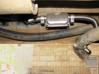
Pieces of stainless steel combustion air exhaust pipe and the muffler were clamped together and attached to the underside of the van, with the end of the exhaust pipe being clamped to the end of the vehicle's exhaust.
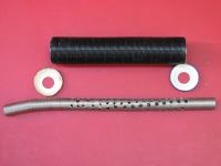
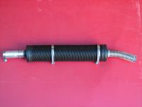
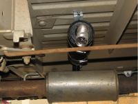
The length of aluminised paper air inlet pipe was anchored to the underside of the vehicle. Operation of the full system confirmed that there was a fair bit of higher frequency noise outside the van. A SBMCC Forum post by CampinGazz described how to make a combustion air intake silencer to deal with this noise. Since I had plenty of exhaust pipe and hot air ducting left over, I made one out of those. I drilled numerous 6 mm diameter holes over a 300 mm length of the exhaust pipe. Two jam jar lids were pressed into service as end caps to the 300 mm length of ducting, after drilling them to accept the exhaust pipe. Upon assembling the parts, the space between the pipe and duct was packed with fibreglass ceiling insulation. The whole was then finished with anticorrosion paint. An aluminium sleeve was made up to clamp the new silencer to the end of the combustion air inlet pipe, and the silencer was fitted under the van floor at right angles to and above the vehicle's muffler.
The effect of the inlet silencer is dramatic; only a soft low frequency growl is audible outside the van now.
Installation Completed
With a shaped piece of 2.5 mm checkerplate aluminium sheet installed as a cover over the access hole for the main unit of the Airtronic heater, the installation was complete.
After double checking all wiring and lines, I first tried running the heater fan from the mini controller. This worked as expected. I then moved on to starting up the heater in heating mode. Listening to the fan and the ticking of the fuel metering pump and watching an ammeter on the house battery, I observed the heater system advance through the stages as described by the Operation Flow Chart and Function Diagram. The heater started up without hesitation! Success.
Lessons Learnt
There is a lot of discussion on the Web about installing the diesel heater. Some of this is old, out of date, or irrelevant to the present reality:
- the fuel metering pump ticking noise is in fact quite low, perhaps due to the rubber mounting block
- the requirement to have a continuous rise to the heater for the fuel delivery tube does not seem to be relevant with the fine bore tubing used
- the impedance of the hot air ducting seems not to be a significant issue in the present installation
- the startup current requirement (8 Amp) is apparently much lower than in the past; wire gauge is not so important.
Useful information from the Web included the suggestions to:
- drill the Ducato fuel tank entry plate for the heater fuel pick-up line, though the information was not entirely correct, and the experience problematic
- install a fuel filter as a precaution
- prime the filter and fuel metering pump and lines
- make and install a combustion air inlet silencer.
I would like to have:
- added an air return silencer - the noise of the heater fan via the hot air inlet duct is the only significant (but low) noise source in the van. This could have been done using the raised floor cavity as the silencer space!
The suppliers of the installation kit should:
- as an option, supply the mini controller rather than just state that they are comfortable with what they supply
- remove the pages and pages of irrelevant electrical wiring diagrams
- spend some time reordering and improving their "Operating Instructions and Service Book".
Air Return Revisited
I noticed that there was some build-up of fluff in the hot air outlet in the shower room. This and mention by others that the heater fan blades and bearings eventually become covered in dust, and other debris unless the return air vent is filtered, has caused me to revise the setup of the air return.
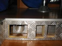
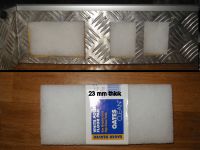
To maintain a low airflow impedance, the new air return is much larger than before, made up of
two louvre vents installed in the checkerplate side of the raised floor. Behind the louvre vents
"Oats" brand white floor cleaning pad material, 23 mm thick, from Bunnings, is wedged into the cavity
holes. The original air return duct is cut short by about 75 mm and the end, which still pokes
through the RSJ, is covered in a disc of air return filter material held in place by a neoprene
rubber strap. This is shown in the picture at right.
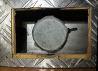
I investigated several materials for the louvre filters. Auto shops sell corrugated flat air filters. However, they would have to be cut up and somehow sealed and supported around the edges to be used here. They also are really unnecessarily fine. The Oats floor cleaning pad is as good as many in its ability to filter fluff, dust and debris.
On a trip to Canada, I found some genuine air return filter pads. They are supposed to be changed every 12 weeks (of continuous use). I am using a piece to cover the inlet duct end just in case some debris under the raised floor might enter the heater fan. However, that material is not self-supporting and is much less effective than the floor cleaning pad at filtration, so I am confident with what I am using.
The filters will need to be serviced occasionally, depending on heater use. I will start with 12 monthly and see how that goes.
Now, it is much harder to inadvertently block the air return with a tissue or somesuch. And an unexpected benefit is that the (low) fan noise through the air return is quieter than before.
LINKS
- Eberspächer http://www.eberspacher.com
- Espar http://www.espar.com
- Dometic Australia http://www.dometic.com.au
- CARAC http://www.carac.com.au
- Autoteile-Discount24 http://www.autoteile-discount24.de
- Self Build Motor Caravaners Club http://sbmcc.co.uk/forum/
Heater Installation
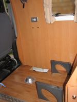
The raised floor behind the driver's seat with table and rear seats removed. A hole for the heater is cut into the Applause below the table.
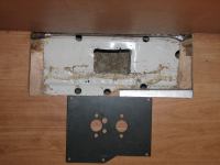
The hole for the heater. (A cable for the reversing cameras is at the van wall, wrapped in Aluminium tape.) The mounting plate is cut to fit the space. Holes for five spring toggle bolts are ready.
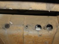
Under the van, holes in the box channel for (from left) wires for fuel metering pump, fuel line, combustion air inlet, combustion air outlet.
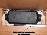
A trial fitting of the heater unit. Width clearance is very tight due to the presence of an RSJ for the rear seats mount.
To fit the hot air inlet ducting, holes had to be cut through the raised floor wall, an RSJ (!) and two ply joists.
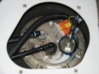
An inspection cover in front of the passenger seat gives access to the Ducato fuel tank. The Airtronic fuel pick-up pipe is sealed into a hole in the top plate, next to the sender connection for the fuel level meter.
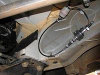
The fuel metering pump in its rubber mounting block. A Z15 fuel filter is installed in the inlet line. The white line is looped before feeding to the combustion unit.
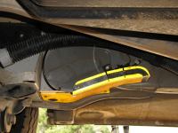
A tough Aluminium stone guard protects the fuel metering pump and lines. The fuel supply line is further protected by split flyscreen spline (not shown).
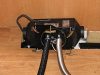
Heater unit with all lines attached, bolted to its mounting plate with spring toggles ready to go into position
The main heater unit installed, awaiting connection of the ducting. The twin fuse block for the heater is fitted below the floor as shown (lower right corner of the access hole.
Centred on the exhaust muffler, this pic shows the combustion air exhaust pipe, combustion air intake pipe, fuel pipe and fuel metering pump wiring entering the box channel below the main unit of the Airtronic D2.
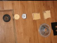
The parts made up for the new combustion air intake silencer.
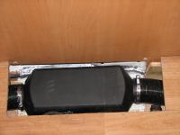
The assembled air intake silencer, ready for installation under the van.
The installed air intake silencer. A bit of stainless steel pot scourer is put in the end of the intake to discourage insects.
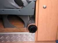
The completed installation with the heater unit below the checkerplate, the air return (inlet), and the house hot air outlet.
The revised house hot air outlet with surround and heat shield under seat.
Revised heater air return. Shortened inlet duct and cutouts for the filter blocks behind louvre vents.
Revised heater air return. Filter blocks in position. Filter material is a floor cleaning pad.
Revised heater air return. Louvre vents installed in the wall of the raised floor.
