Cabin Inside
Centre Console
The centre console switches are in a different order to the original Daily 4x4. On the left are the Diff Lock activation switches - the labels show which diff is being activated by a press. On the right are:
- Heated Mirrors switch
- Radiator Fan Off switch – for traversing deep water
- a double light switch: Overhead Light (upper), Flood Lights (lower)
- a double light switch: High Beam Extras (upper), unused (lower)
- ABS OFF light (upper), CHECK diff lock pump (lower)
Accessory and USB sockets in the glove box shelf.
Power in Cabin
The Twin Accessory/Dual USB sockets in the shelf above the glove box are always ON and powered by the starter battery (take note).
Glovebox Door
The hinge for the glovebox door just has to be a joke played on us by Iveco. After a lot of rough-road travel the door fell off! Two long cable ties and some carefully located holes and the door stays in place while still functional. If the door needs to be removed to give access to, for example, the Body Builders Connections then the cable ties can be cut. Extra cable ties are kept in the glovebox.
Overhead USB Point
Two USB charging sockets point downward. A third (not visible) points forward. One powers the dashcam on the windscreen. Two rear-view screens are there too.
The cab courtesy light unit in the centre of the overhead parcel shelf has a recess behind the cover that is very suitable for a USB charging point. Powered from the courtesy light wiring, it is only working when the ignition is on or lights are on. This may be good for such things as a dashcam which is only operated during vehicle activity.
Note that plugs using the downward pointing USB sockets are vulnerable to knocks as we move into and out of the cabin from the camper. So for things that tend to leaving the plug in, a single USB socket pointing to the front of the vehicle is also available.
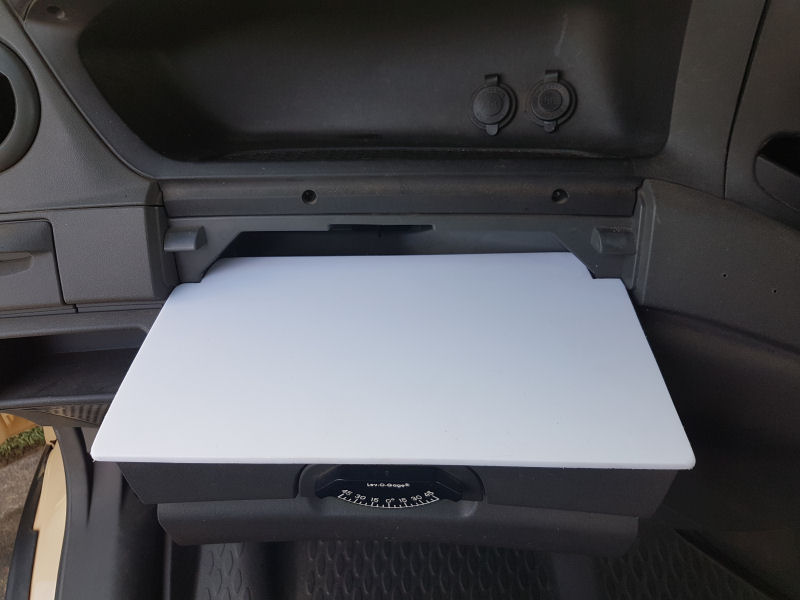
A Tablette for the Cab
A flat surface in the Daily cabin makes the area more usable for a cup, bowl or notebook when camped up — a flat surface such as in this photo!
We keep this "tablette" in the LH door pocket, ready for use.
TX3100 UHF Radio
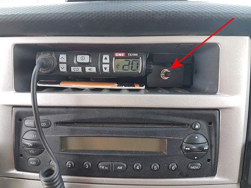
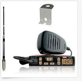
A GME TX3100 80-channel 5watt UHF Radio now resides in the centre console bin. It was supplied with a quality spring-mounted 6.6dBi antenna.
A simple circuit in a black plastic box next to the Radio keeps the radio powered whenever the ignition is on and for a set period (9 minutes) once the ignition is off. Its possible to also power up the radio for the set period at any time: just press the switch on the box.
Cabin seats swivelled to make a sitting room in the front.
Seat Swivels
Swivels under the cabin driver's and passenger's seats were a great feature of our previous Avan Applause. By turning the seats inward, and to the rear, they effectively doubled the usable space in the motorhome. Because the connection between cabin and camper in TT30 is not full height and the seats are very close to the cutout, swivels would not be as effective, but still seemed worthy.
Having installed seat swivels in TT30, I have found that it is quite difficult and of little benefit to turn the driver's seat. The floor-mounted gear sticks interfere. The swivel for the passenger seat is useful, but the seat needs to be set forward before attempting to turn it.
Cabin Outside
Warning Horn
For a more impressive horn noise, activate the "Air Horn" button on the bank of switches below the centre console switch bank.
Snorkel
The RidgeLine Snorkel feeds the engine with fresh air well above road grime and heavy bulldust. The snorkel also provides a safe high-level air intake when attempting deep-water crossings.
Fitting the snorkel was a bit of a challenge; several mistakes were made due to very poor instructions. Beware that removal of the snorkel U-tube in the engine bay will require cutting through the joint with a long thin knife well lubricated with soapy water.
Cabin Inside - technical
Power in Cabin
The NARVA Item 8114 Accessory/Dual USB socket consumes about 2mA compared with 12mA for the BL version with blue LED in the USB socket. They are positioned in the only area with a clear space in the framework.
The sockets are connected to the +12V truck supply through a 10A fuse and Pin 6 of the Body Builders 20-Pin Connector (see power connections for more information).
A Tablette for the Cab
The Daily cabin is remarkable for its lack of anywhere flat. This can be rectified:
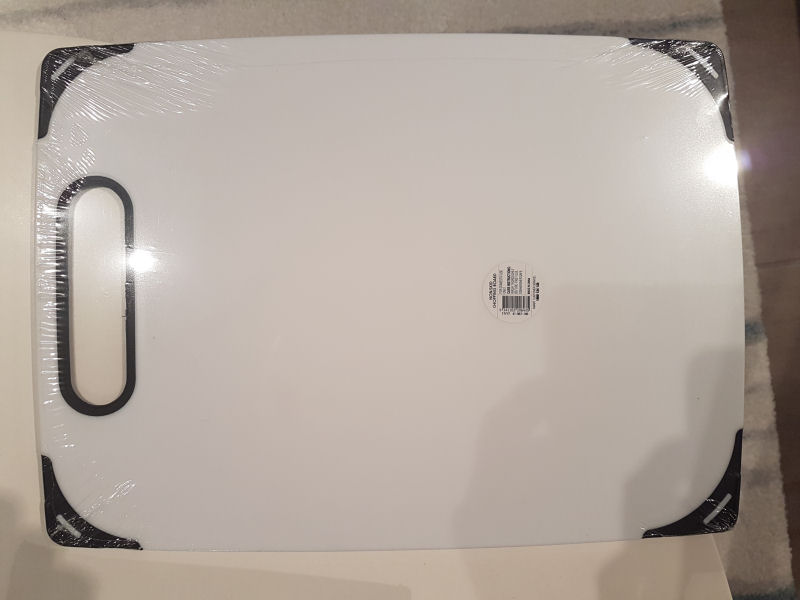
A thin white cutting board from Kmart is the material for the tablette.
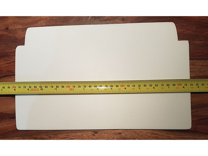
The board is cut to size using a hand saw. It is a neat slide fit into the glove
box.
Make a cardboard template first.
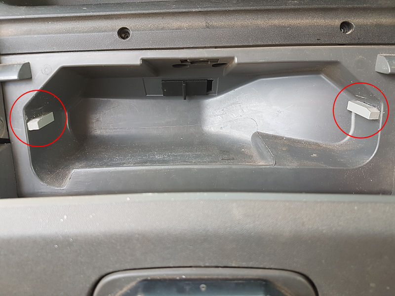
Blocks of PCV are superglued to the sides of the glovebox, set down by the thickness of the board. This for stability.
Glovebox Door
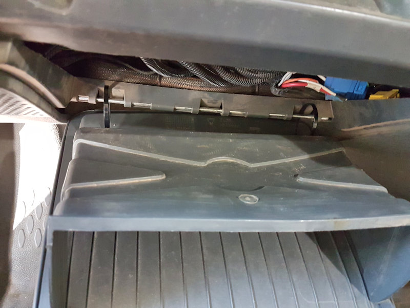
Threading cable ties through the glovebox door holes and around the long hinge pin. Long cable ties makes this an easy job.
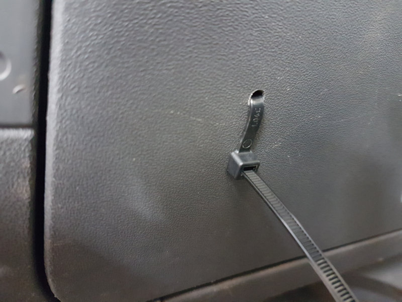
One cable tie is snugged up, ready to be cut to length
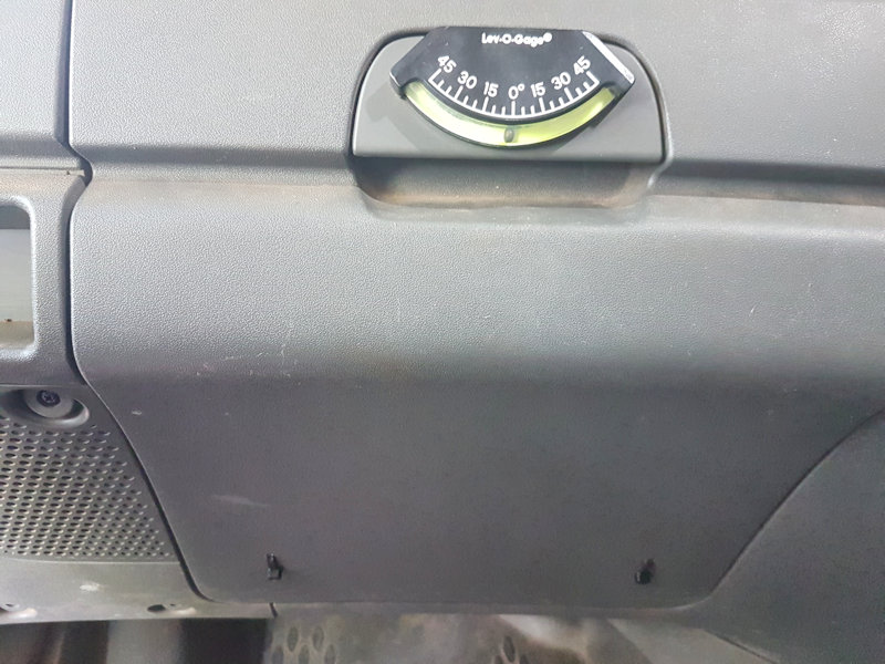
Glovebox door closed with cable ties in position low down. The Lev-O-Gage from Whitworths shows tilt of TT30.
Overhead USB Point
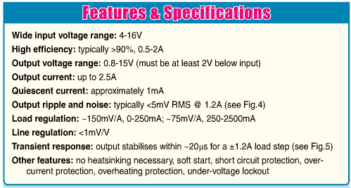
Silicon Chip magazine for July 2015 (pp36–44) featured an article "Install USB charging points in your car" and has a kit available. Unlike the commercial USB charging points for an accessory socket, the kit has a very low quiescent current of ~1mA, about 10 times lower than the plugs, and can be installed in the courtesy light unit.
A hole for a double 180° USB socket (from an eBay supplier) was made in the cover for the courtesy light and the socket glued in place with urethane adhesive. While there, I replaced the 15W 42mm festoon bulb with a 16-LED lamp, and the 5W T10 bulb with an LED equivalent (see Cab Lights. This reduced the power consumption and heat dissipation in the luminair considerably.
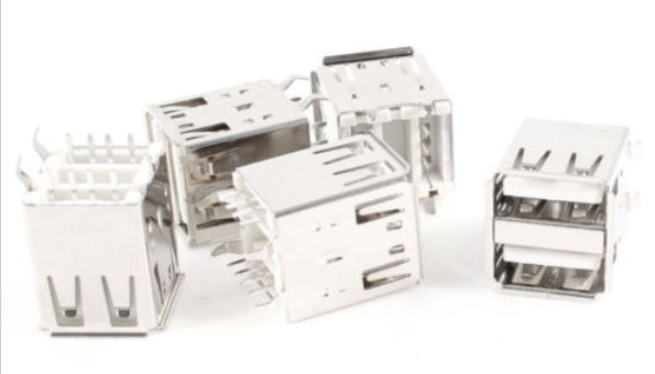
One of these double USB sockets is glued into a hole in the light cover. The centre two pins were shorted together.
Soldering up the USB charger kit was a bit of a challenge, since it was my first experience with surface-mount components. It went together quite easily. I covered the whole circuit board with a length of black heat-shrink tubing, joined up power wires to relevant parts of the light board and lodged the charger behind a notch above the USB socket. It fits very well.
Back of overhead luminaire, showing back of new USB points with circuit board adjacent in black heat-shrink. Forward USB point is circled.
The back of luminaire in the overhead parcel shelf, showing connections to the light power tracks. (Forward USB port not installed.)
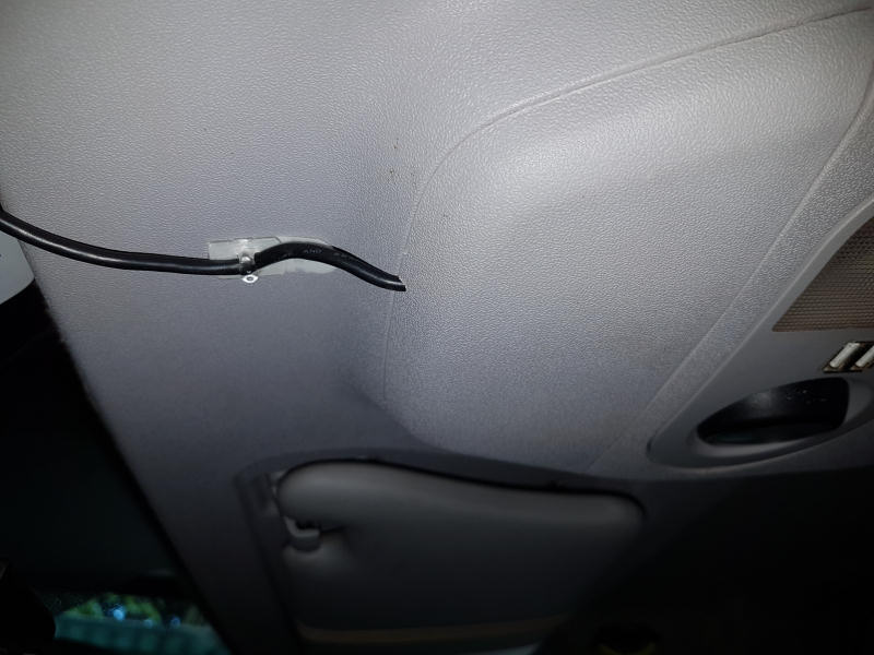
A cover in place with cable from forward USB point exiting.
TX3100 UHF Radio
A lug on the bull bar accepts the bolt for the UHF antenna. The coax cable, sheathed in 7mm dia. split conduit, passes into the cabin through the large rubber cable entry gland above the starter battery and then over to the upper bin in the centre console where originally the diff. lock switches and lights were.
New power connections, both ignition-switched and always-on, were also fed to the vacant upper bin. There the diminutive TX3100 is fitted to a bracket. Rear plugs, a remote speaker above the driver, and the microphone are plugged in. Radio operation is documented here.
TX3100 Anytime ON
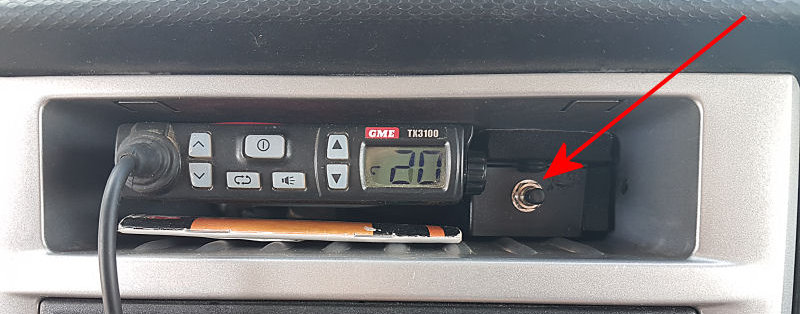
If the radio is powered from the Always-On feed there is the possibility of inadvertently leaving it on, possibly flattening the starter battery. But powering from the Ignition-Switched feed means that the radio is off as soon as the ignition is turned off. The solution is a simple circuit that keeps the radio powered whenever the ignition is on and for a set period once the ignition is off. Its possible to also power up the radio for a set period at any time.
The circuit to do this fits in a small box with a push-button on the front. Briefly pressing the button provides power to the radio for almost 10 minutes. Pressing the button again at any time extends the power for a further 10 minutes.
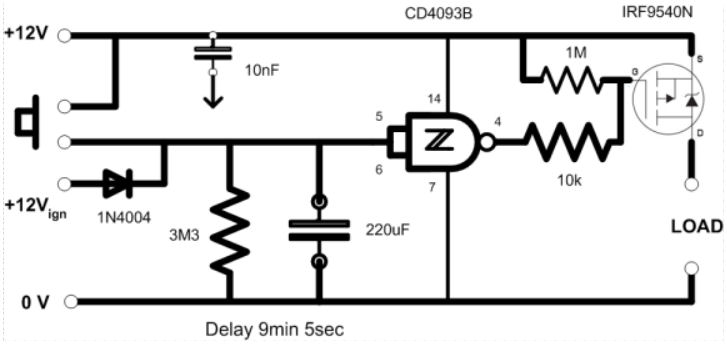
The circuit uses a CMOS NAND device with Schmitt-trigger inputs to monitor the voltage across an R-C pair with time constant of about 10 minutes. When that voltage decays to a low value the device output, which was low, goes high and switches off the p-Channel MOSFET to cut off power to the UHF radio.
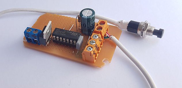
Blue connector for LOAD, orange connector for power inputs.
I use just one of the four NAND devices in a CD4093B quad 2-input NAND gate with Schmitt Trigger. The CD4093B does not need a special power supply: it is powered directly from the starter battery. The MOSFET is a IRF9540N. It is capable of handling huge current, but here it only needs to switch a maximum of less than 1Amp (the LOAD). It and all other components come from Jaycar.
Seat Swivels
I bought two seat swivels, Driver Swivel SB4244 and Passenger Swivel SB4234, from Melbourne Trucks, an Iveco agent. They are ADR3 Compliant, and have been registered against TT30's VIN number by the seller. The particular swivels are very solid, are 26.5 mm thick, and having an open centre allows electrical cables to turn with the seat. They are manufactured by Transport Seating Technology in Queensland.
The swivels are designed to bolt under the seat slides so that the seats, when swivelled towards the centre of the truck, would be able to slide into and away from the centre. However, I had specified TT30 to have both seat frames lowered by 50mm and this meant that the driver's seat swivel has to be located on top of the seat slide. The controller for the Daily differential locks under the seat is too high to do otherwise.
Because the turntable for the driver's side has the pivot much further back than for the passenger side, the result is that the turntable plate now attached to the seat extended too far forward, obstructing leg movement. And the mounting holes for the M8 high tensile countersunk bolts were now in the wrong positions. These issues were overcome by sawing off about 85mm of the plate and drilling new mounting holes. These changes do not compromise the integrity of the seat swivel in any way. The seat slide engagement lever also had to be shortened.
Driver's seat frame. The diff lock manager components are practically flush with the top of the slides.
Modified Driver's Swivel to fit above the slides.
Driver's swivel in position.
The swivel for the passenger's seat was also mounted on top of the slides after drilling new holes.
Cabin Outside - technical
Headlight Breathers
The headlights, mounted low in the bumper bar to meet ADR requirements, have a breather tube that can allow water in when fording creeks. Once the light cluster is removed for access, its a simple matter to push a length of garden sprinkler tube with a cap to keep out bugs into the breather tube and route it high.
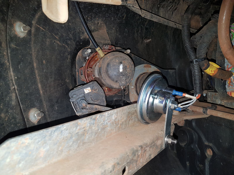
A length of black sprinkler tube inserted into headlight breather. A new Auxiliary Horn is in the foreground.
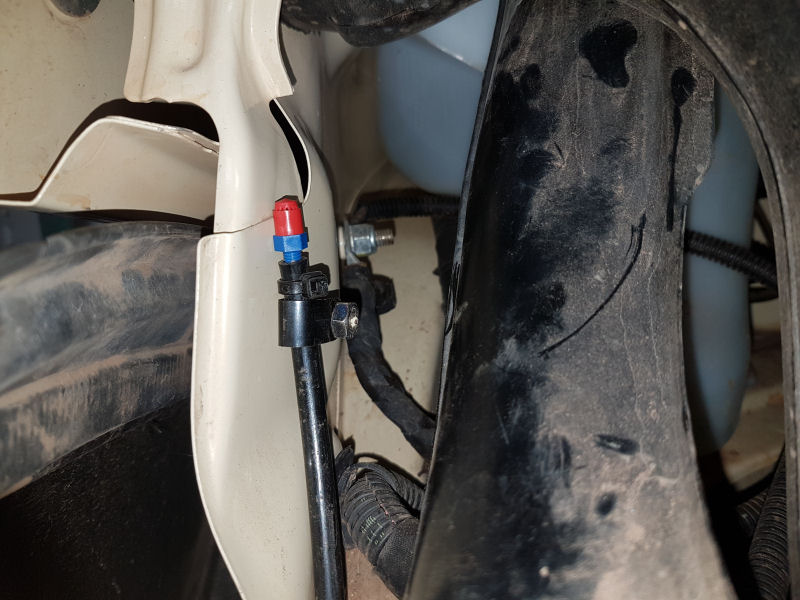
The black tubing is routed behind the right light cluster, capped with a red sprinkler head.
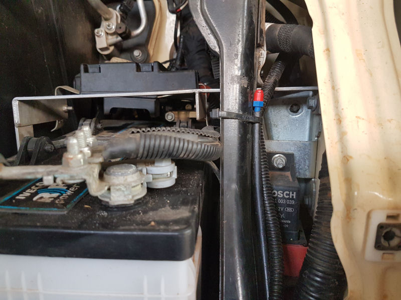
The black tubing is routed behind the left light cluster, capped with a red sprinkler head.
Warning Horn
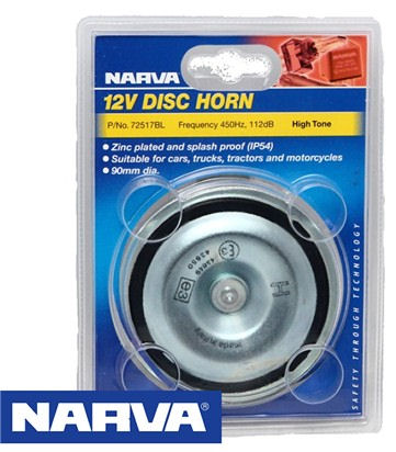
The camper Touch Screen has provision for an Auxiliary Horn to sound in emergencies, it just needed one. Further, the CAN-Bus switch console in the cabin below the centre console switch bank has a button labelled "Air Horn". When that is turned on the Auxiliary Horn sounds along with the twin OEM horns when the horn button on the steering wheel column is pressed.

Wiring was in place for the horn albeit incorrectly done at the 12-Pin Body Builders' Connector. It took some time to figure out the error but once found I routed the green "HN" signal cable to Pin 7 of the 12-way Connector and plugged a High Tone Narva 12V horn into the "HN" power cable that was under the left headlight cluster. The horn is bolted to a bracket behind the left bumper bar.
Snorkel
Setting out where the large hole in the mud guard was to go.
The installation instructions for the snorkel were minimal, based mostly on poor quality photographs. The first step was to mark out where the large hole in the side of the guard for the air tube was to be. Checking and rechecking before drilling the pilot hole and bolt holes took a while before I was convinced all was OK.
With the guard removed from the truck, the hole for the air tube was drilled
and enlarged using a jig-saw. Enlarging the hole in the inner guard was
harder, as the metal vibrated a lot. There are a few videos of snorkel
installation on YouTube and unlike occurs in at least two of them, I did not
slip nor cut the holes in the wrong places ![]() .
.
Enlarging the hole in the outer guard.
The inner guard is cut away to allow the air tube to pass through.
The air tube joins to the air filter box. Its a poor design. See text for discussion of the red arrow.
Fitting the air tube with its remarkable "U" bend to enter the air filter box was a challenge. First I had failed to remove the splash guard in the wheel well, but once corrected, access was easier. Then I had failed to remove the flow sensor in the bottom of the filter box, so did not have as much movement as was desirable. Two strips of sticky backed foam were supplied, but I failed to see that BOTH should have been used to join the air tube to the air box. Instead, one strip and a copious amount of black silicone sealant and a couple of tek screws held them together. At least water is not going to find its way past that! If/when the air box needs to be removed, the silicone (red arrow) will have to be cut with a long sharp knife and lots of soapy water and replaced upon reassembly.
Next day, the snorkel was bolted to the outer guard, the second foam strip was applied to the outer end of the air pipe, lots of silicone sealant was added, and the guard and snorkel offered up to the air pipe and the guard was bolted in place. It sort of all worked, but I am not totally convinced that it is water tight.
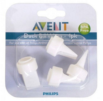
The air filter box has two peripheral drain holes in the base. One drain hole has a heavy duty duck bill valve designed to let water out but not in. The other drain hole had a dubious plug of silicone "sealing" it; I replaced this with a replacement duck bill valve for a Philips Avent Breast Pump bought from eBay. It fitted over the second drain hole easily. I now have a lifetime supply of replacements.
LINKS
