The VT2500 toilet in the Applause
A'van fitted a Dometic VT2500 vacuum toilet with ceramic bowl in the Applause. This system allows for much flexibility in layout as the waste cassette can be some distance from the toilet bowl. Further, chemicals are not needed for the system to operate (but see below).
The VT2500 has worked well for four years, so long as

- the flush ball and seal in the ceramic bowl are kept clean and free of pieces of paper, wind-blown leaves, grains of sand etc so that water is retained in the bowl at all times
- The O-rings on the base station are well lubricated with silicone grease to maintain the
vacuum for at least 12–24 hours. The important O-rings are
- the D=13 x 2 mm O-ring on the vacuum pump-out spigot ("a" in the photo below) and
- the D=45/38.5 x 6.8 mm double O-ring on the waste discharge port ("d" in the photo below)
- in warmer weather, daily addition of a teaspoonful of generic nappisan (sodium percarbonate) hastens decomposition and greatly reduces any strong smells when emptying the cassette.

Problems and their Solutions
Buckled O-Ring in Waste Cassette
The first O-ring on the plunger in the entry port on the waste cassette became badly pinched. This would not affect the normal operation of the toilet, but it would eventually lead to leaking of contents when the cassette is removed from the base station. This needed repair.
Upon undoing the six 8 mm AF bolts holding the entry port in place and withdrawing the port, I noticed the O-ring seal was missing, even though the cassette is grooved to take one (a mystery).
To get the plunger out of the entry port, I levered the end cap off using a pair of multigrips — this broke the fairly weak glue bond that held the cap in place. The photo shows all the parts including the mangled first O-ring on the plunger.

I only had 39 x 3 mm O-rings and the mangled one is a little smaller so I swapped the rear one on the plunger to the front and used what I had in the rear position. The side entry hole of the waste entry port can be seen in the photo. I think it was the sharp edges of this hole that had caught on the O-ring and pinched it. A bit of time with a fine "half round" file smoothed the leading and trailing edges of the hole. The improved performance of the plunger sliding in the port proved that this is a good idea.
The entry port was reassembled using a soldering iron to weld the end cap back on. A new 60 x 3 mm O-ring ($3.30) came from a supply house and I assembled the entry port to the base station using silicone grease on the O-ring.
Vacuum Switch Housing Snorkel Broken
While we were travelling, the VT2500 suddenly started to cycle every ~10 minutes.
With a finger over the port of the vacuum pump-out spigot ("a" in the photo above of the base station) and activating the cassette-present recognition switch ("b" in the photo above of the base station), gave rapid cycling of the pump, showing a leak in the vacuum switch housing or the vacuum pump valves.
To remove the pump assembly, I undid the four Philips-head screws that retain a thick rubber plate holding the pump onto the rear of the base station. The pump came out fairly easily — big problem, in retrospect it should not have.
I checked the pump valves (inlet above, outlet below) and cleaned and reassembled the valve flaps using a little talcum powder. I greased the O-ring around the main diaphragm using silicone grease and reassembled the pump.
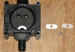
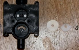
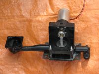
It was only when I went to reinstall the pump that I realised that what I thought was a part of the pump housing was actually a part of the vacuum switch housing. It looks like a tapered tube in the photo:

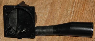
The vacuum switch housing has a conical snorkel that extends down to the pump where it engages using an O-ring seal. This snorkel had snapped off when I removed the pump - in fact ALL OF the vacuum switch housing, pump, and exhaust joiner have to come out and go in position as a single assembled item.
Examination of the break showed a score mark all around, and some tiny missing pieces suggesting that the break (or perhaps only a fracture crack) had actually occurred in service, and the parts were only being held in position by compressive force.
The vacuum switch housing is available from a Dometic agent as a spare part #242600456 at a cost of "around the $25 mark" but would have to be ordered in. What I cannot understand is why the vacuum switch housing is constructed as it is. The main part of the housing is rigidly bolted to the base station and connects via the snorkel to the pump that is very flexibly mounted. So the snorkel is always flexing in service and is surely a break waiting to happen.
I decided to repair the break, reasoning that a "flexible" repair would make the vacuum housing better than new, able to absorb vibration. Aligning the parts, I used a soldering iron to weld them together. After smoothing the joint, I tightly wrapped the area with Nitto tape and in turn wrapped that with self-amalgamating rubber tape. The photo shows the vacuum switch housing with repaired snorkel, the vacuum pump, and the exhaust joiner all together ready to be offered up to the base station. I realise that the welded joint may well break, but I am hoping that the tapes will continue to provide a good, flexible, seal.
I reassembled the base station and tested the vacuum. The "finger over port" test passed. However, the toilet cycled every hour or so. Not good enough.
Leaking Pipe Seals
I observed that there was a very soft swishing noise coming from somewhere on or near the base station. I had heard it before but it was louder when the toilet was in rapid cycling mode and I reasoned the noise was due to vacuum leaking away. So there was a leak and it was audible.
The white Rehau piping intentionally has several sharp bends to break up the waste. In the Applause there are 12 joints from the toilet bowl to the base station, and eight of these are readily accessible. I reasoned that perhaps they are TOO accessible and have been disturbed too much by all the packing and unpacking that we do under the bed in the storage area that has this piping passing through it.
I disassembled the eight accessible joints, cleaned the pipes and the O-rings, and regreased both the pipe joint seats and the O-rings with silicone grease. I noted the poor seating for the last O-ring, the one that goes into the base station, but I could not see how to improve it and pressed on.
With it all back together, a test of the toilet gave NO SOUND and a vacuum that has lasted about 22 hours.
A Kill Switch for the VT2500
My wife hates being woken in the night so regardless of the vacuum hold performance, the VT2500 cannot now be trusted and a kill switch is needed. Problem is, with a simple kill switch its too easy to forget to turn it off after turning it on to establish vacuum. Something cleverer was needed.
The result: a circuit that is activated by a two-way switch, centre off. One way (latched down) turns the VT2500 on and keeps it on. The other way (momentarily up) turns it on only for 30 s, enough time to fully establish a vacuum (maximum of about 15 s is needed).

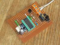
The circuit to do this is fairly simple. An R-C timer feeds into two CMOS NAND gates (with Schmitt trigger activation) in series to control a power MOSFET that switches the power to the VT2500.
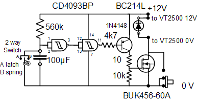
With the control switch off, the output of the second NAND gate is high, keeping the transistor off which in turn keeps the power MOSFET off. So there is no power to the VT2500.
When the control switch is momentarily pressed upward, the timing capacitor is shorted out so the input to the first NAND gate is low and the transistor is turned on which in turn turns on the MOSFET that switches power on to the VT2500 and so the vacuum pump starts. Meanwhile the R-C timer has started. The R and C values chosen result in the output of the NAND gates going high 30 s later, turning off the VT2500.
If the control switch is latched on downward then the timing circuit is disabled and power is retained to the VT2500. (An override switch is included on the circuit board so that the VT2500 can operate normally if so required.)
The component values all appear to be sensible. The particular power MOSFET was at hand. The BC214L is a PNP transistor used for switching and amplifier applications. In case the VT2500 motor is connected directly across the power line, I use a 1N4148 diode to quench switching spikes. A 47 μF capacitor is wired across the power supply lines to reduce any noise.
The power MOSFET has to handle approx. 1.8 A continuous and about 8 x this at startup. Current consumption without the kill switch was about 14 mA on standby. It is now < 2 mA in kill mode.

The control switch is the same as used in the roof-status monitor; it is a modified mini-SPDT centre-off spring-return both sides (Jaycar #SK0987). I have removed the spring and bridge from one side of the mechanism to make the switch a spring return one side, latching action the other side.
LINKS
- Dometic RV Centre http://www.dometicrvcentre.com.au
- Jaycar http://www.jaycar.com.au
VT2500 Toilet
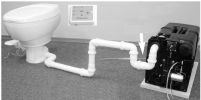
The complete VT2500 system, showing the bowl, Rehau piping and base unit with waste cassette. The controller is inset.
Repaired vacuum assembly: (from the left) switch port, repaired snorkel, vacuum pump and motor, outlet connector.
The kill switch circuit board for the VT2500 vacuum toilet. Construction is on strip board.
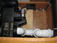
Looking down on the VT2500 base station with the kill switch circuit board mounted in a box near the motor. The control switch is 3 m away.
