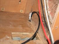
Changes to the Fridge Installation
The Vitrifrigo Model C85i 90 litre fridge with Danfoss BD35F compressor consumes approx 4 A peak, with a duty cycle of approx 50% at 20°C. The Danfoss BD35F controller module is code type 101N0210 and is fitted with a 277 Ω resistor in series with the thermostat unit, thereby setting the motor speed to 2,500 rpm.
Although on delivery the fridge seemed to work well enough, inexplicably it was ventilated from floor level and under the van floor into the motorhome room! Any dust stirred up on dirt roads was circulated into the house through the fridge vent — a really silly installation that had to be changed either by venting the fridge outside or by sealing off the outside air intakes and circulating indoor air alone. For the second case, the added heat load to the van interior would be less than 50 W, not much. Either solution would require fan forcing the ventilation air. Although a lot more work, arranging for the ventilation air to exhaust outside was the chosen fix. This allows better use of the space behind the passenger seat since we do not have to be concerned about blocking the exhaust with hanging clothes or foldup chairs, etc. which we store there.
A New Air Vent for Fridge
The Supplied Ventilation Setup
Ventilation is important to effectively remove the heat pumped out of the fridge. The power module for the compressor is extremely reliable as long as it is properly installed and does not overheat; a cooling fan for the module itself is sometimes recommended.
A'van set up the fridge in a cabinet behind the passenger seat. Air comes in at floor level (through a gap of about 20 mm at the base and the full width of the fridge) and from two under-floor vents that are close to the engine exhaust pipe and have screen mesh to keep out insects — these are approx 150 mm x 40 mm in size. So the air intakes add up to about 255 sq cm, which is a bit less than the required (by Danfoss) 300 sq cm.
The design had air exhausting through a plastic vent approx 150 mm x 200 mm on the side of the fridge cabinet behind the passenger seat. The Danfoss compressor unit has a 120 mm fan that sucks air across the condenser. The fan sound is noticeable when it is on. It runs all the time that the compressor runs. The Danfoss fan was mostly just stirring up the air in the small space behind and below the main fridge compartment; any through-flow ventilation was mostly by natural convection.
An External Exhaust Vent
Since I had some at hand and the space was available, I glued builder's "Foilboard" (10 mm thick polystyrene covered in aluminium foil), to the inner sides and top of the cabinet. This included covering over the hole for the plastic exhaust vent in the side of the cabinet.
At a later date, I added a further 10 mm layer of Foilboard to the sides of the cabinet and glued a layer to the top and back of the fridge itself.
The new exhaust vent is 150 mm high by 225 mm wide, a double-fluted aluminium louvre unit with an effective ventilation area rather smaller than this. Since I planned to install fans too, this smaller area would not be a problem. The size of the vent determined the size of the cutouts in the cabinet and the side of the Ducato: the cutouts need not be bigger than the vent effective area.
I sawed a 125 mm x 250 mm rectangular hole in the back of the cabinet for the new exhaust arrangement; marked out the required hole in the side of the van (avoiding any obvious issues with the structure) so that it was slightly higher than the hole in the cabinet, and covered the paintwork around the hole markings with gaffer tape; drilled out the corners of the hole and cut the rest out with a power jigsaw. All rather traumatic but it went well. I then fashioned from 1 mm aluminium sheet a duct between the hole in the back of the cabinet and the hole in the side of the van so that all exhaust air would leave the van rather than recirculate inside it. Then painted the cut edges of the side with zinc chromate and glued the duct in place with silicone adhesive.
Fan-Assisted Ventilation
The Danfoss Instructions (78 kB PDF doc) note that, referring to the diagram below,
A fan (5) can be connected between the terminals + and F. Connect the plus to + and the minus to F. ... The fan output can supply a continuous current of 0.5Aavg. A higher current draw is allowed for 2 seconds during start.
Ventilation fans can thus be run directly from the fridge and I will not need a thermostat to turn them on and off since the ventilation fans will be most effective when the condenser fan is running.
I bought two CoolerMaster BlueLED silent 120 S13 fans ($35.00 for the pair). These are 120 mm computer case fans rated at 40 CFM, a noise level of less than 20 dBA, and a current consumption of 160 mA at 12V for one, 320 mA for the two in parallel, and 85 mA for the two in series. The compressor fan supply is able to cope with the two in parallel. They are practically silent — far far quieter than the Danfoss compressor motor and fan, which is not loud anyway.
The fans are controlled by a switch on the Fridge Monitor panel. A circuit diagram (see below) shows how. The switch connects the fans to the 12 V supply either in parallel (high speed) or in series (low speed). A link behind the panel can be set to have the fans not run, run all the time or only when the compressor is running. It is set to run with the compressor.
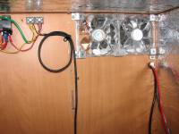
The case fans are held in the cabinet cutout by some brackets bent up from aluminium flat. The fans each have four blue LEDs and when they are running, the light from these LEDs can be seem through the outside vent - an unwanted and rather eerie appearance at night!
Ventilation Air Inlet Vents
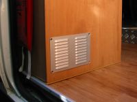
Extensive travel on dusty roads showed that the air inlet vents under the van let a lot of dust into the house. I had expected that the circulation fans would pump any dust back out through the new external exhaust vent, but this was not entirely so. So now, the in-floor inlets are closed off with polystyrene blocks. A louvre vent, the same size as the external exhaust vent, is now fitted to the side of the fridge cabinet adjacent to the entrance, low down in line with the fridge condenser and fan. A block of filter material, the same as used in the holes for the diesel heater air return (viz "Oats" brand white floor cleaning pad from Bunnings), is wedged into the 130 x 200 mm hole behind the louvre vent. The filter acts to reduce noise from the fridge fan, as well as providing cooling air filtration.
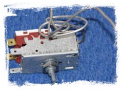
Fridge Thermostat
The fridge thermostat (7, see diagram below) has its sensor clipped to the upper right side of the U-shaped cooling plate which makes the freezer compartment. Its overly long tube was stuffed behind the cooling plate, touching it in several places. The result seems to have been that the thermostat was switching the compressor unreliably, resulting in a failure to keep the fridge at temperature, especially if frost built up on the cooling plate.
I rerouted the thermostat tube so that it is contact with the plate only at its end, in the clip. The tube is coiled and taped to the inside plastic wall of the freezer compartment. This change has made a big difference to the setting required for a desired temperature. The thermostat is now set at a much lower number and cold temperatures are well maintained.
Fridge Monitoring
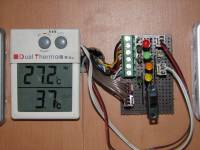
While the fridge was out of its cabinet, I installed an indoor-outdoor LCD thermometer. The existing interior light was connected by a two-core cable running inside the side of the fridge, directly from the 12V supply. A piece of 4-core telephone cable is the same diameter, so I used the light cable to pull through the 4-core. Two cores supply the interior light and a small interior fan, and two cores go to the thermometer sensor. The only issue is that the telephone cable is single-strand so it is imperative to not nick it when stripping the insulation - a nick will develop into a break sooner or later.
The LCD thermometer is mounted on the van wall with an extension cable to the fridge-mounted sensor - the performance of the thermometer is not affected by some extra cable. The thermometer was powered by an LR44 1.5V alkaline cell. Now it runs from the house battery. This is effected by powering a 12 kΩ resistor in series with a red LED from the 12V battery. The voltage drop across the particular LED chosen is 1.5V and is practically independent of house battery voltage. The LCD thermometer is wired in parallel with the LED and so is supplied with a stable 1.5V (~4% change for a 20C temperature change).

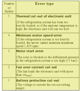
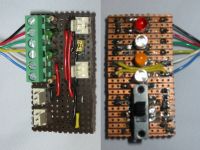
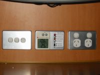
Along with the LCD thermometer, I also installed a circuit board that controls the ventilation fans and monitors the fridge activity. From the front panel, the ventilation fans can be set to run in fast mode or in slow mode.
The Danfoss instructions note that if an LED is wired at (6), ie between + and D on the fridge panel at the rear of the fridge, then an error state can be reported as a series of flashes of the LED repeated every 4 seconds.
A set of four LEDs on the monitoring panel above the fridge cabinet shows power on (red, provides power to the thermometer too), compressor on (green), error state by sequence of flashes (orange), and ventilation fans on (blue).

Controlling Compressor Speed
The value of the resistor (8), as shown in the Danfoss compressor diagram above, determines the compressor speed and thus the performance of the fridge. Its default value is 277 Ω, giving a compressor speed of 2500 rpm.
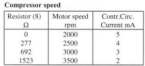
The minimum speed is 2000 rpm with zero resistance for (8). The Danfoss data sheet gives COP (Coefficient of Performance) figures: basically energy out (for cooling) divided by energy in (for turning the compressor). Since I have observed a current consumption of 4 A at 2500 rpm, it appears the COP (EN 12900) has been about 1.32.

I have added a DP3T miniature slide switch (DSE Product Code P7614 - limited stock, Altronics has a larger version) to the Fridge Monitor panel. It is wired to switch resistances of 0, 280 and 1000 Ω in place of the Danfoss 277 Ω resistor. Measured at the fridge, the resistances are 2, 273 and 1020 Ω. The lower position is intended for running the fridge overnight - more efficiently, longer run times; the middle position is normal operation; and the upper position is for faster pull-down when a load is added to the fridge - less efficient, higher current.

With the fridge empty and running off the house battery, the measured performance of the fridge is shown in the Table. The amplitude of the temperature cycle is largest for the low speed condition (2.5°C) and smallest for the high speed condition (1.1°C), as is the duty cycle. At each switch position, the current consumed decays through the on-cycle by about 25% and averages 2.9 A at the lowest speed (overnight) position, 3.9 A at the mid-speed (normal) position, and 5.3 A at the high speed (pull-down) position.
As the Table shows, the saving in current drain for the overnight setting (lower speed) is substantial: 18%, and the penalty for operating at the higher speed, is also large: 16%. It remains to be seen whether these changes occur in practice with a loaded fridge.
Taking the COP for normal operation from the Danfoss tables, viz 1.32, we can calculate the energy required to keep the fridge cold over a day: 766 Wh for the dial setting used in the test. And assuming this is the same for both overnight and pull-down speeds, we can work out the COP for those speeds: 1.61 and 1.13 respectively. If the COP had changed only due to compressor speed change, the average current consumption would have changed only by about ±5%.
Air Circulation in the Fridge
A fan in the fridge can be useful in circulating cold air throughout the cabinet, though to do that well requires quite a lot of energy. The fan can reduce ice build-up on the cold plate and helps maintain a more constant temperature.
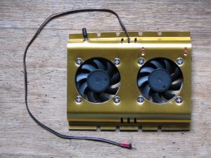
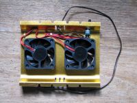
A DealExtreme dual cooling fan, designed to cool hard disk drives, is ideal for the task. Mounted vertically on the back wall of the fridge, it blows air up behind the cold plate that forms the freezer and downward to the rest of the fridge. Its frame protects the fans from fridge contents being pushed too close.
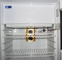
I installed a switch, wired the same way as for the fridge ventilation fans (see circuit diagram), into the frame so that the dual fans can be set to run in parallel or series. Running in series appears to be adequate and reduces power consumption too: current is approx 56 mA. Power comes from the fridge light switch supply. The fans run all the time the fridge receives power. I added a miniature slide switch in the light housing to turn off the fridge light and the fans. The wiring can be seen in the photo of the fridge with circulation fans in place.
Voltage Drop at the Fridge
The fridge is powered via the Shaudt Elektroblock at Block 1, pins 2 (+ve) and 4 (-ve) and a 20 A fuse. The D+ signal from the vehicle alternator is used to switch a relay in the Elektroblock to provide power from the alternator when available. If the D+ signal is absent, power comes from the house battery.
When the fridge was running off the house battery, measurement showed that the voltage drop at the fridge was 0.65–0.68 V . Is this a problem? After all, the fridge started and ran well enough. Since the fridge is comprehensively managed by a electronic controller module and can operate at supply voltages down to 10 V (default cut-out voltage 9.6 V, cut-in voltage 10.9 V), so long as the battery voltage is above about 11.5 V the fridge would run.
The guru of small BD compressors, Richard Kollmann, in discussing failures of the Danfoss fridges notes that:
Troubleshooting one of these units is simple once it is understood that it is very unlikely that this type compressor will ever fail. BD compressors have almost an unlimited life because their control module protects it from failures common in other hermetic electric compressors. The number one cause for a Danfoss BD compressor module to terminate a compressor start up is a low voltage spike. Voltage spikes at module are not always visible with a meter and can be present on any [motorhome]. Unstable voltage is why the module must receive power direct from battery buss using correct size wiring, fuses, circuit breaker and switches that allow no voltage drop. When the compressor is correctly wired to the battery buss it will absorb voltage surges like a very large electrical capacitor reducing module electronics false starts and module failures.
So the voltage drop to the fridge needs to be as small as practicable so the battery itself acts not only as an efficient power source, but also as a large filter of voltage spikes.
The Wiring for the Fridge
The wiring from the Elektroblock to the fridge is ~8 AWG twin cable, and this is over a 7 m length when account is taken of the installation. But it is the wiring to the battery that is the interesting thing! The Elektroblock and 12 V house wiring was installed floating, grounded only at one place in the engine bay to the starter battery negative: negative return wiring is used consistently, following best practice to avoid effects of faulty ground connections to the chassis. There are three cables from the Elektroblock to the engine bay, each over 7.5 m in length: i) the D+ signal cable (a red wire), (ii) a ~10 AWG twin cable to the battery cutoff relay in the engine bay via the fuse block there, used to power circuits when the alternator is operating, and to charge the starter battery when the Elektroblock is connected to mains power, and (iii) a ~10 AWG twin cable to the starter battery via the fuse block there, used to power the fridge circuit when the alternator is operating.
Consider the case when the engine is running. The diagram shows how this was installed.
 The positive wire length is approx. 14 m, going from the
fridge to Elektroblock Block 1 Pin 2 and then out to the starter battery/alternator from Block 2
Pin 1 on the Elektroblock. The negative path length is similar, going from the fridge to
Elektroblock Block 1 Pin 4 and then out to the starter battery/alternator from Block 2 Pin 4. These
are rather long runs, but since the supply voltage is a high approx. 13.6 V (the alternator voltage),
some voltage drop matters little to the operation of the fridge.
Now for the case when the engine is stopped and the fridge was powered from the house battery:
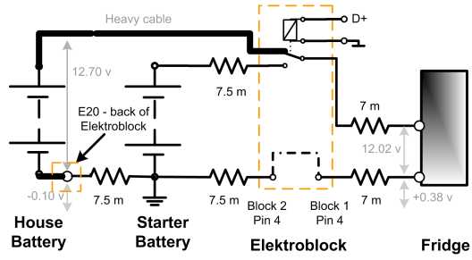 The positive path length is now only 7 m, since the connection
between the Elektroblock and the house battery uses heavy cable (1.5 AWG — see
details here).
But the negative path length is now 22 m — From the fridge, the negative wire goes to Block 1, pin 4 of the Elektroblock, and out Block 2, pin 4 to the starter battery, and then immediately back to the rear of the Elektroblock to Block E20 where it is joined to the heavy cable to the negative of the house battery. With the fridge operating on the house battery supply of 12.7 V, the voltage between fridge negative and chassis was measured as +0.38 V, and between house battery and chassis as -0.10 V.
That is, the voltage drop at the fridge when operating was 0.68 V and 0.48 V of this is due to the long negative path.
This extraordinarily long negative return path length for the fridge and the voltage drop when
powered from the house battery is cause for concern as it means not only is the margin between supply
voltage and fridge cut-out reduced, the fridge is excessively isolated from the battery and not protected
from voltage spikes. It can be eliminated if the fridge and house battery are grounded to the chassis.
The alternative, use much heavier twin cable between Elektroblock and starter battery, is too much trouble.
The problem with grounding to chassis is the connection — chassis grounds often deteriorate and
become high resistance points. Nevertheless, this is the fix implemented here, as shown in the following
diagram:  The fridge and house battery ground connections are shown. For the
fridge ground, I found a convenient plug hole and plate in the Ducato steel floor below the cabinet. I
drilled it out and tapped it to accept a long 3/8" galvanised bolt. This passes up into the plywood floor
of the cabinet where nuts, castellated washers and plenty of grease are used to secure an 8 AWG grounding
cable.
Now measurements show only a 0.15 V drop between house battery and fridge on load — acceptably small ensuring the fridge operates well at lower house battery voltages and is protected from voltage spikes by the battery itself.
LINKS
- A'van http://www.avan.com.au
- Deal Extreme http://www.dx.com
- Vitrifrigo http://www.vitrifrigo.com/eng/
- DSE http:www.dse.com.au
- Altronics http://www.altronics.com.au
Fridge Changes
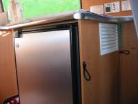
The problem: the ventilation air for the fridge exhausted into the van from the side of the cabinet wall.
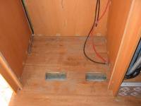
The two ventilation inlet vents in the floor of the fridge cabinet, along with some of the dust that was brought in with the ventilation air.
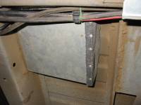
One of the two air inlet vents under the van, protected by a mesh.
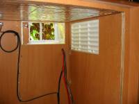
Looking out through the new ventilation exhaust holes in the cabinet and the side of the van. Foilboard on the ceiling of the cabinet; old vent yet to be covered.
Case fans in position. All foilboard in. Wiring for Omni-Step on wall.
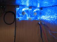
Ventilation fans on.
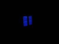
Ventilation fans on at night.
Revised fridge cooling air inlet louvre vent.
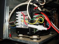
Power and auxilliary cables added to fridge control box. A 5 A inline fuse protects the power line to the fridge monitor.
Prototype of the fridge monitor on the wall above the fridge cabinet. 3.7° in the fridge.
The final fridge monitor circuit is built on Vero Board. The LEDs and Switch are moved to the track side of the board.
Fridge Monitor installed. 2.5° in the fridge, fans are on in slow mode. A brushed aluminium Clipsal front plate is used as a mount, in keeping with the power plates.
A dual fan mounted on the rear wall of the fridge. It blows towards the wall. Wiring to the fridge light is on the right.
Rear view of the fridge circulation fans with switch wired to give parallel or series operation.
A grounding wire between the fridge negative line and the steel chassis of the Ducato reduces voltage drop.
