The Sliding Door
A visit to a Fiat dealer elicited advice that the second (centrally located) door handle fitted by A'van could lead to an expensive breakdown in the door mechanism over time. When the door is opened from the outside (or from inside using the handle hidden by the fridge compartment) the central door handle also activates and hits the side of van. This places an extra load on the opening mechanism and over time can lead to a breakdown.
The dealer also mentioned that the cable release that unlocks the sliding door from its fully open position needs to have some free play, to again relieve extra load on the door opening mechanism.
The Cable Release
In this case, there appears to be no issue with undue tension on the cable. However, the cable release had failed to work on three occasions, twice "repaired" by a Fiat dealer. The simple, and so far effective, fix is to use a small cable tie to keep the cable end properly located in the plastic keeper of the door opening mechanism.
Door Openers
A'van had installed the opening activation rod from the central door handle by simply clamping it to the rod from the principal door handle. Thus when the latter handle was used, the central door handle also operated. The fix is simple, but awkward to implement due to access issues.
We want the central handle activating rod to move only when that handle is operated; if the principal handle is operated, the central handle rod should not move.
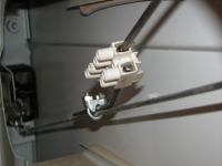
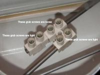
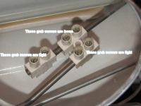
To achieve the desired behaviour, I cut the central handle activating rod in half, and reclamped it to the main rod so that the two cut ends overlap by about 30 mm. Expediency led me to use two pieces of 30 Amp connector block instead of something more purposeful. Connector block conveniently already has grub screws to clamp cable in its holes. The two-hole piece is fitted to and clamped firmly to the piece of the central handle activating rod that is also clamped to the main mechanism rod. Then the other piece of activating rod is threaded through the other hole of the connector block so that 20 mm or so of rod protrudes. A single-hole piece of connector block is firmly clamped to that piece of rod. With a bit of adjustment, that's all there is to it. A picture describes this better.
These changes introduced some rattles that have been cured by glueing some felt and some foam carpet dampener material to the inside of the panels near the rod mechanism.
Sliding Door Intermediate Stop
 It is often nice to be able to keep the sliding door half
open on site. On sloping ground, and perhaps on the flat, an intermediate positive stop for the door is
necessary. Easy enough since there is already a bolt in the lower door track that can be used to position
a stop bracket.
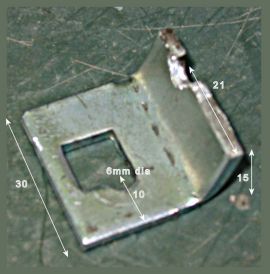
I made a suitable bracket from some scrap 2 mm galvanised steel flat. The square hole is unnecessary (it was in the metal already). The notch in the tang is necessary to allow the door mechanism to pass over the stop.
Sliding Door Mechanism
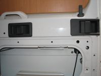
The sliding door with the lining removed, showing the principal and central (added by A'van, on the left) door handles
Showing the modified activating rod from the central handle. Two pieces of 30 Amp connector block are used.
When the central handle is used, the single piece of connector on the activation rod pushes against the two-hole piece, pulling on the main activation rod and so releasing the door.
When the central handle is released, its activation rod slides free of the main activation rod and so allows the main handle to release the door independently.
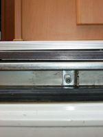
The new intermediate door stop in position, secured by an existing 5 mm bolt.
The sliding door held at the intermediate stop. The entrance way is fully clear.
